
Sub-pixel level corner detection method and system

A sub-pixel level, detection method technology, applied in the direction of measuring devices, instruments, optical devices, etc., can solve the problem of low missed detection rate and multiple detection rate of corner points, low detection accuracy, and it is difficult to ensure the accuracy of corner points. Issues such as pixel-level coordinate accuracy can reduce the influence of noise and improve accuracy and precision

Inactive Publication Date: 2019-01-15
BEIJING INFORMATION SCI & TECH UNIV
View PDF6 Cites 5 Cited by
  • Summary
  • Abstract
  • Description
  • Claims
  • Application Information

AI Technical Summary

Problems solved by technology

Although the quadratic polynomial approximation method is simple and direct, insensitive to image noise, and has a low rate of missed detection and multiple detection of corner points, the detection accuracy of this method is lower than that of the gray center method and the gray center of gravity method, and it is difficult to meet the small Sub-pixel accuracy requirements in the process of micro-calibration of hole centering system
[0007] To sum up, in the microscopic calibration of the micro-hole centering system, it is necessary to extract the sub-pixel-level coordinates of the corner points of the micro-black and white checkerboard calibration plate, and the existing sub-pixel-level corner point detection methods are difficult to guarantee the corner point extraction. The accuracy rate and the accuracy of sub-pixel coordinates of corner points

Method used


Image

  • Sub-pixel level corner detection method and system
  • Sub-pixel level corner detection method and system
  • Sub-pixel level corner detection method and system

Examples


Embodiment Construction

[0041] Embodiments of the present invention are described in detail below, examples of which are shown in the drawings, wherein the same or similar reference numerals designate the same or similar elements or elements having the same or similar functions throughout. The embodiments described below by referring to the figures are exemplary only for explaining the present invention and should not be construed as limiting the present invention.

[0042] The sub-pixel-level corner point detection method and system according to the embodiments of the present invention will be described below with reference to the accompanying drawings.

[0043] Image 6 is a flow chart of a sub-pixel-level corner point detection method according to an embodiment of the present invention.

[0044] like Image 6 shown, combined with Figure 1 to Figure 5 , according to an embodiment of the present invention, the sub-pixel level corner detection method includes the following steps:

[0045] S601: ...


PUM


Abstract

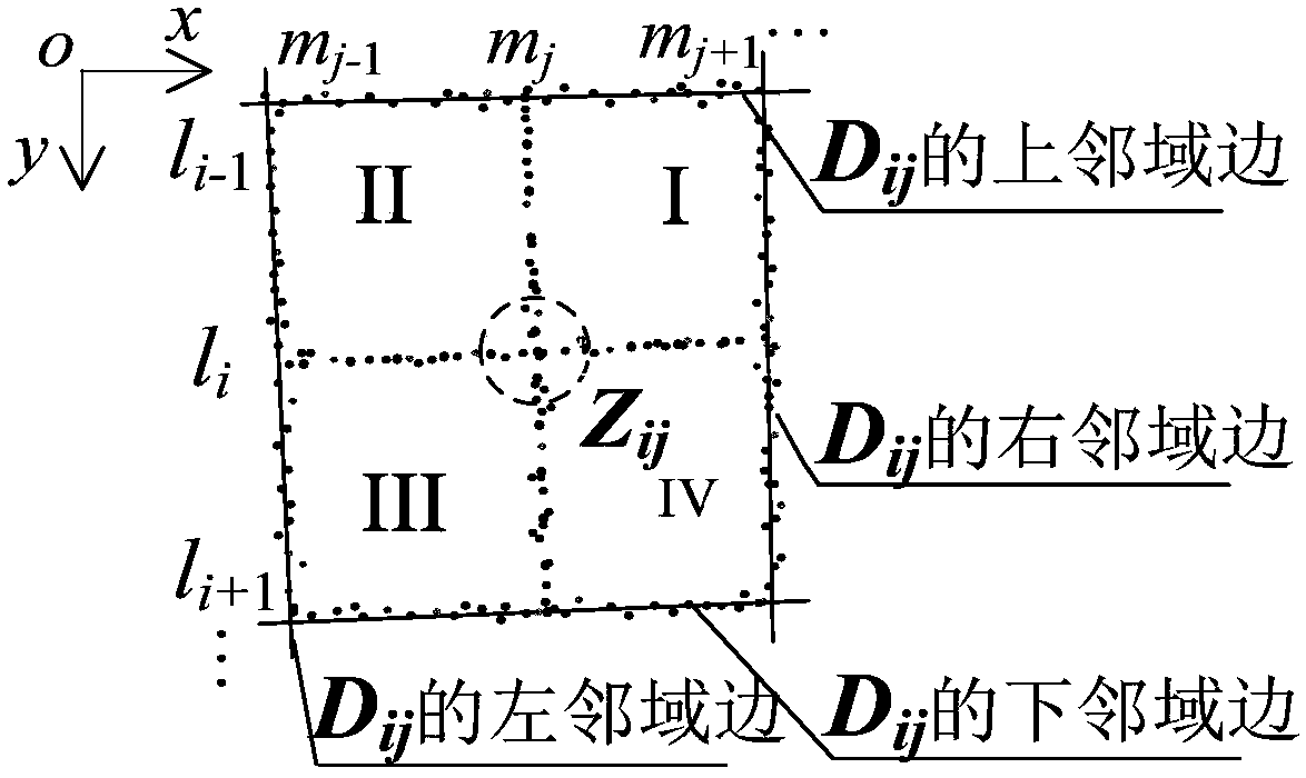
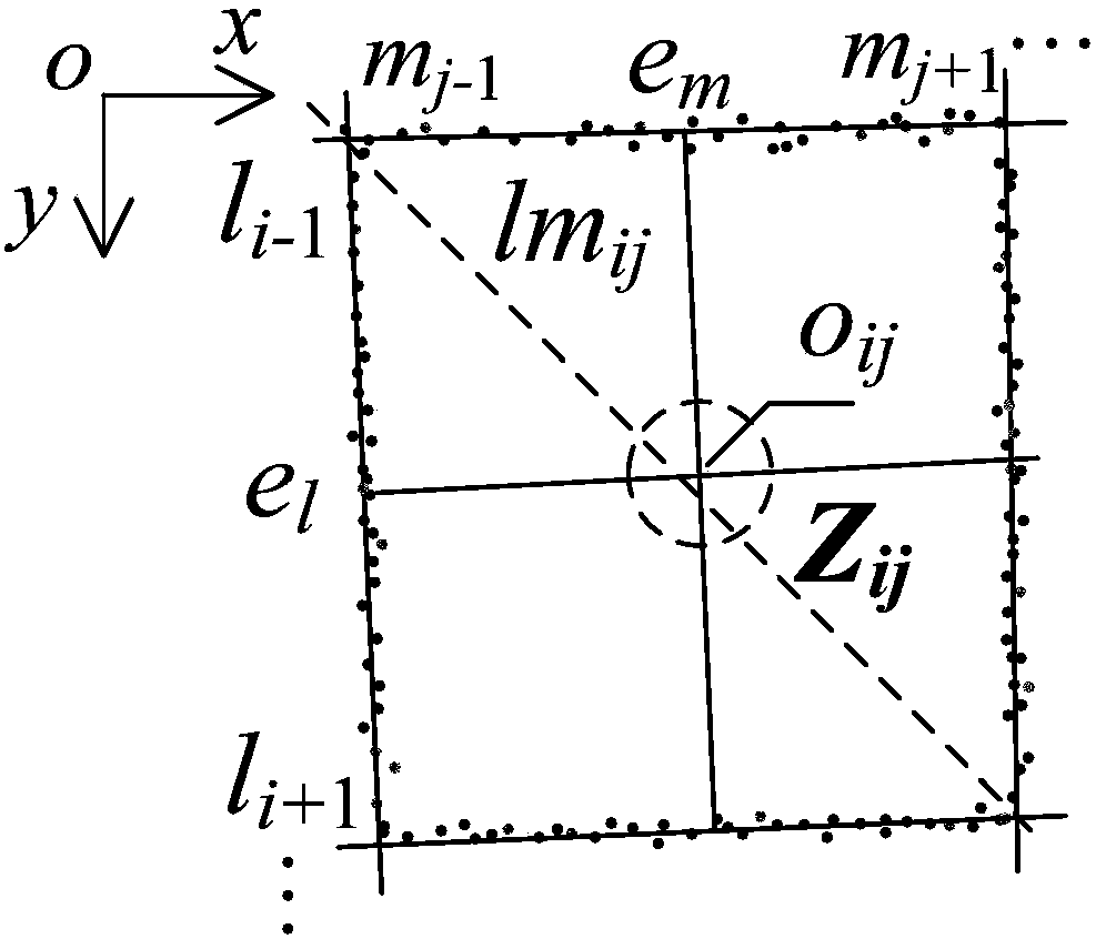
The invention discloses a sub-pixel level corner detection method and a system. The method comprises: providing a calibration plate, and acquiring an image of the calibration plate; preprocessing theimage to obtain a first image; performing edge extraction in any four neighborhood D<ij> of the first image, and fitting four neighborhood edges in the four neighborhood D<ij> to obtain a linear equation of the four neighborhood edges; obtaining coordinates of an equidistant point O<ij> in the four neighborhood D<ij> according to the linear equation of the four neighborhood edges; obtaining a direction of the diagonal of the four neighborhood according to the linear equation of the four neighborhood edges in the four neighborhood D<ij>, wherein the diagonal is one of the two diagonals of the four neighborhood D<ij> with a lower average gray-scale value; using a SINC function gray-scale distribution to constrain a corner position to obtain a sub-pixel level corner within a domain segment ina four-neighborhood diagonal direction over the equidistant point O<ij> in the four neighborhood Dij. The sub-pixel level corner detection method reduces the influence of noise on the image acquisition of the calibration plate, and effectively improves the accuracy and the precision of sub-pixel corner detection.

Description

technical field [0001] The present invention relates to the technical field of sub-pixel level corner point detection, in particular to a sub-pixel level corner point detection method and system. Background technique [0002] With the rapid development of advanced manufacturing technology, the demand for metal parts with tiny holes in high-end equipment continues to grow. Among them, the surface quality and shape accuracy of tiny holes play a vital role in the service life and stability of metal parts. At present, the common processing route for micro-holes with a diameter of 0.1-1 mm is as follows: firstly, micro-vias are processed by EDM with micro-columnar electrodes, and then secondary processing is performed by electrolysis with side-wall insulating hollow columnar electrodes. Electrolytic secondary machining can remove burrs and thin the remelted layer, and also repair surface micro-cracks after EDM, thereby effectively improving the shape accuracy and surface quality...

Claims


Application Information

Patent Timeline
IPC IPC(8): G01B11/00
CPCG01B11/002G01B21/042
Inventor 孔全存骆荣坤刘桂礼樊夏辉李东
Owner BEIJING INFORMATION SCI & TECH UNIV
Learn More