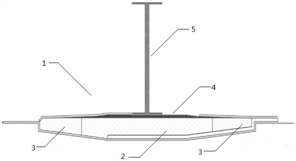
A kind of wind power blade and its manufacturing method
A technology for wind power blades and manufacturing methods, which is applied in the field of wind power blades and their manufacturing, can solve problems such as the inability to guarantee the quality of glass fiber and core material layup, the difficult manufacturing process of the shell, and the uncontrollable distribution of glue content, etc., to achieve saving The effect of removing bonding and curing time, improving product quality, and making the production process less difficult
- Summary
- Abstract
- Description
- Claims
- Application Information
AI Technical Summary
Problems solved by technology
Method used
Image
Examples
Embodiment 1
[0042] 1) On the beam mold, lay the lower surface guide net and the lower surface release cloth in sequence, with a density of 150g / m 3 Polyethylene core material (core material chord laying width is 50mm, thickness is 5-50mm), surface density is 1600g / m 2 Girder fiberglass fabric with a density of 1000g / m 3 Place the web on the upper surface of the glass fiber cloth, control the gap between the web and the upper surface of the glass fiber cloth to ≤0.1mm, and then lay the upper surface release cloth on the web and the upper surface of the glass fiber cloth to guide the upper surface Air-pumping bags on the net and the upper surface, and then lay a sealed vacuum bag film on the entire girder mold, so that the girder mold after the web is placed as a whole forms a vacuum system, vacuuming, so that the vacuum degree is ≤ -0.098Mpa and can maintain vacuum negative pressure Not less than 30 minutes, then inject the resin system into the molding cavity through the injection port w...
Embodiment 2
[0046] 1) On the beam mold, lay the lower surface guide net and the lower surface release cloth in sequence, with a density of 80g / m 3 Polyethylene terephthalate core material (core material chord laying width 50mm, thickness 5-50mm), surface density 1000g / m 2 The beam carbon fiber fabric with a density of 1250g / m 3 Place the web on the upper surface of the glass fiber cloth, control the gap between the web and the upper surface of the glass fiber cloth to ≤0.1mm, and then lay the upper surface release cloth on the web and the upper surface of the glass fiber cloth to guide the upper surface The net and the upper surface pump the bag, and then lay a sealed vacuum bag film on the entire girder mold, so that the girder mold after the web is placed as a whole forms a vacuum system, and the same operation method as in Example 1 is used for vacuum infusion of resin and curing molding. Obtain the prefabricated part of the girder web;
[0047] 2) Lay the lower skin reinforcing mate...
Embodiment 3
[0050] 1) On the beam mold, lay the lower surface guide net and the lower surface release cloth in sequence, with a density of 200g / m 3 The balsa wood core material (core material chord laying width is 50mm, thickness is 5-50mm), surface density is 1800g / m 2 The beam carbon fiber fabric with a density of 800g / m 3 Place the web on the upper surface of the glass fiber cloth, control the gap between the web and the upper surface of the glass fiber cloth to ≤0.1mm, and then lay the upper surface release cloth on the web and the upper surface of the glass fiber cloth to guide the upper surface The net and the upper surface pump the bag, and then lay a sealed vacuum bag film on the entire girder mold, so that the girder mold after the web is placed as a whole forms a vacuum system, and the same operation method as in Example 1 is used for vacuum infusion of resin and curing molding. Obtain the prefabricated part of the girder web;
[0051] 2) Lay the lower skin reinforcing materia...
PUM
| Property | Measurement | Unit |
|---|---|---|
| density | aaaaa | aaaaa |
| density | aaaaa | aaaaa |
| density | aaaaa | aaaaa |
Abstract
Description
Claims
Application Information
 - Generate Ideas
- Intellectual Property
- Life Sciences
- Materials
- Tech Scout
- Unparalleled Data Quality
- Higher Quality Content
- 60% Fewer Hallucinations
Browse by: Latest US Patents, China's latest patents, Technical Efficacy Thesaurus, Application Domain, Technology Topic, Popular Technical Reports.
© 2025 PatSnap. All rights reserved.Legal|Privacy policy|Modern Slavery Act Transparency Statement|Sitemap|About US| Contact US: help@patsnap.com

