Al technical title is built by PatSnap Al team. It summarizes the technical point description of the patent document.
A technology of abrasive jet and cutting machine, applied in the direction of abrasive jet machine tools, abrasives, abrasive feeding devices, etc., can solve the problems of polluting the environment, leaving hidden dangers, time-consuming and labor-intensive problems, and achieves small size, convenient operation and wide application range Effect
Active Publication Date: 2020-11-24
BEIJING HAILAN HUAXUAN TECH
View PDF5 Cites 0 Cited by
Summary
Abstract
Description
Claims
Application Information
AI Technical Summary
This helps you quickly interpret patents by identifying the three key elements:
Problems solved by technology
Method used
Benefits of technology
Problems solved by technology
The traditional methods are fire isolation, abandonment and burial, chemical replacement, etc., which are not only time-consuming and laborious, but also pollute the environment and even leave hidden dangers for a long time
At present, there is no emergency rescue device integrating fire protection and cutting to solve this problem
Method used
Image
Click on the blue label to locate the original text in one second.
Reading with bidirectional positioning of images and text.
Examples
Embodiment Construction
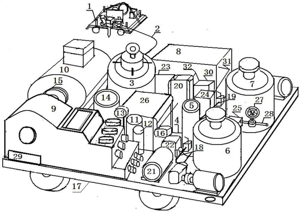
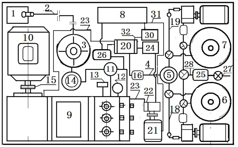
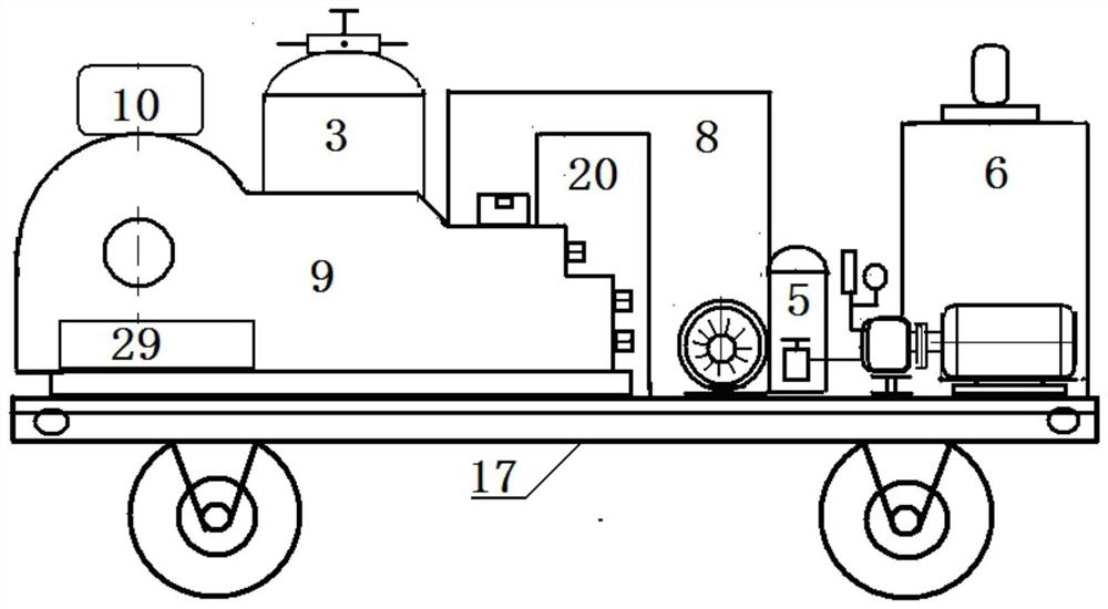
[0038] Figure 1( Figure 1A , Figure 1B , Figure 1C ), (1) fire-fighting cutting head assembly described in the embodiments of the present invention, (2) high-pressure pipe, (3) abrasive mixing tank assembly, (4) foam liquid supply pipeline, (5) foam liquid Mixing valve, (6) A liquid supply assembly, (7) B liquid supply assembly, (8) Cutting machine power distribution cabinet, (9) Booster pump, (10) Explosion-proof motor, (11) Foam liquid unloading Relief Valve, (12) Foam Relief Valve, (13) Pressure Gauge, (14) Foam Accumulator, (15) Coupling, (16) Foam Filter, (17) Foam Assembly Base Frame, (18) A liquid pipeline, (19) B liquid pipeline, (20) heat exchanger, (21) circulating pump frequency modulation motor, (22) circulating pump, (23) circulating pipeline, (24) hot oil filter device, (25) inlet filter, (26) pressure compensator, (27) inlet main gate valve, (28) inlet pipeline, (29) booster pump oil tank, (30) thermal controller, (31 ) Waterproof electric wire, (32) therm...
PUM
Abstract
The invention discloses a movable foam abrasive jet fire-fighting cutting machine. The cutting machine comprises a fire-fighting cutting tool bit assembly, a high-pressure pipe, an abrasive mixing tank assembly, a supply pipeline, a mixing valve, a liquid A supply assembly, a liquid B supply assembly, a cutting machine power distribution cabinet, a booster pump, an explosion-proof motor, an unloading overflow valve, a safety valve, a pressure gauge, an energy accumulator, a coupling, a filter, a foam liquid assembly base frame, a liquid A pipeline, a liquid B pipeline, a heat exchanger, a pressure equalizer, a heat-sensitive controller, a hot-oil filter, a liquid inlet filter, a heat-sensitive circuit, a circulating pump, a frequency modulation motor, a three-way gate valve, an oil tank and a waterproof electric wire. The liquid A supply assembly and the liquid B supply assembly are used for pumping liquid A and liquid B into the mixing valve to form foam liquid, then the foam liquid is mixed with abrasive in the abrasive mixing tank assembly after passing through the booster pump, foam abrasive jet is formed, and then the foam abrasive jet is accelerated to a supersonic speed through a nozzle of the fire-fighting cutting tool assembly to impact a to-be-cut object, and fire-fighting foam is generated in the cutting process so as to realize fire-fighting cutting.
Description
technical field [0001] The invention relates to a mobile foam-abrasive jet fire-fighting cutting machine for emergency relief and fire-fighting rescue. Specifically, when cutting dangerous chemicals that are flammable and explosive in the air, or when cutting obstacles in fire rescue, the liquid that can produce fire-fighting foam will be pressurized through the supercharger and mixed with the mixing valve. Abrasives are mixed in proportion and accelerated through the nozzle to form a foamy abrasive jet; this kind of foamy abrasive jet produces fire-fighting foam while cutting dangerous chemicals, covering the cutting edge, thus a device for emergency rescue and fire rescue. This device that integrates fire rescue and emergency rescue is called a mobile foam abrasive jet fire cutting machine. It belongs to the field of fire rescue. Background technique [0002] In the process of production, storage, transportation, use of flammable, explosive and hazardous chemicals, and f...
Claims
Application Information
Patent Timeline
Application Date:The date an application was filed.
Publication Date:The date a patent or application was officially published.
First Publication Date:The earliest publication date of a patent with the same application number.
Issue Date:Publication date of the patent grant document.
PCT Entry Date:The Entry date of PCT National Phase.
Estimated Expiry Date:The statutory expiry date of a patent right according to the Patent Law, and it is the longest term of protection that the patent right can achieve without the termination of the patent right due to other reasons(Term extension factor has been taken into account ).
Invalid Date:Actual expiry date is based on effective date or publication date of legal transaction data of invalid patent.