Fine blanking flange parallel multiple circular groove processing center posttreatment knife handle cutter combination

A machining center and tool handle technology, which is applied in the direction of manufacturing tools, metal processing equipment, metal processing machinery parts, etc., can solve the problems of small cutting amount, time-consuming and labor-intensive guarantee of accuracy, and time-consuming, etc., to reduce tool consumption and improve product quality. The effect of high quality and economic benefit

Active Publication Date: 2019-01-15
江苏鹏德工业科技有限公司
View PDF10 Cites 2 Cited by
  • Summary
  • Abstract
  • Description
  • Claims
  • Application Information

AI Technical Summary

Problems solved by technology

[0002] The end face groove is mainly processed by lathe, but this product is a stainless steel thick flange for the exhaust manifold of a multi-cylinder engine, which is processed by precision stamping, but each large hole has a sealing ring groove, which is difficult to simultaneously Process these sealing ring grooves
If lathe processing is used, special fixtures are required, and multiple clampings are required. For example, the stainless steel thick flange of the exhaust manifold of a 4-cylinder engine needs 4 clampings, which is time-consuming and labor-intensive and requires high cost to ensure accuracy.
When clamping and machining on a machining center, a small-diameter end mill is required. The end mill rotates at high speed and walks along a circular trajectory, which takes too much time. The main reason is that the size of the end mill is small, so The small amount of cutting results in low efficiency and cannot fully utilize the processing capacity of the machining center

Method used


Image

  • Fine blanking flange parallel multiple circular groove processing center posttreatment knife handle cutter combination
  • Fine blanking flange parallel multiple circular groove processing center posttreatment knife handle cutter combination
  • Fine blanking flange parallel multiple circular groove processing center posttreatment knife handle cutter combination

Examples


Embodiment Construction

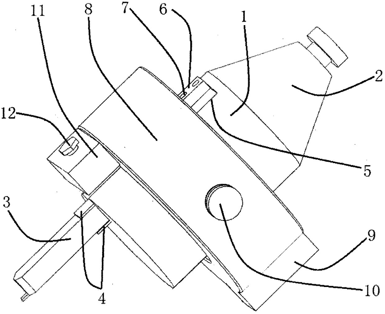
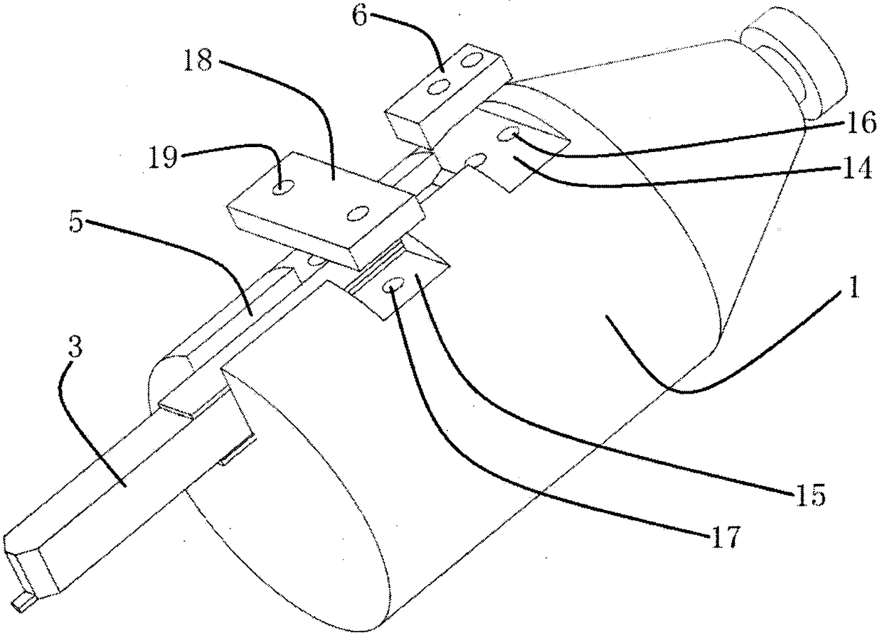
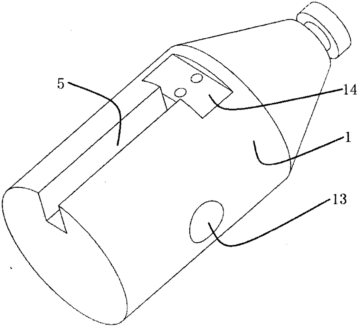
[0015] Refer to attached figure 1 , attached figure 2 , attached image 3 , attached Figure 4 , attached Figure 5 And attached Figure 6 , a fine blanking flange side by side multi-circular groove machining center post-processing tool handle combined structure features: the processed flange 23 has four large holes 25, each large hole has a circular groove 24, such parts as The fixture is very complicated when using a lathe, and every time a circular groove is processed, it needs to be re-clamped, which is time-consuming and laborious. Therefore, the solution of the present invention is adopted. The grooved tool holder 1 has a mounting structure 2 on the machining center. The installation groove 5 of the end face groove cutter 3 has a depth of 40 mm and a width of 15 mm. The end face groove cutter 3 adjusts its position in the installation groove 5 by increasing or decreasing the adjustment pad blade 4, and the thickness of the adjustment pad blade 4 is 0.5 mm. , 1mm an...


PUM


Abstract

The invention relates to a fine blanking flange parallel multiple circular groove processing center posttreatment knife handle cutter combination, which is applicable to the installing, clamping and processing of a plurality of circular grooves on a processing center once, and is particularly applicable to the efficient processing of a plurality of parallel circular grooves with higher precision requirements on a precision punching stainless steel thick flange. The concrete structure consists of a knife handle 1 with a groove, an end surface groove knife 3, an annular press ring 8 with an eccentric mass block, a support shaft 10 with a groove, a pressing screw 12 and a regulating pad knife blade 4, wherein the end surface groove knife is eccentrically arranged in the knife handle with thegroove, and is fixed by a press plate and screws; the cutter position can be precisely controlled by the processing center; a plurality of parallel or concentric circular grooves can be processed on aworkpiece.

Description

technical field [0001] The invention relates to a combination of fine blanking flange parallel multi-circular groove machining center post-processing tool holder tool, which is suitable for machining multiple circular grooves in one clamping on the machining center, especially suitable for precision stamping stainless steel thick flanges High-efficiency machining of multiple parallel circular grooves with high precision requirements. Background technique [0002] The end face groove is mainly processed by lathe, but this product is a stainless steel thick flange for the exhaust manifold of a multi-cylinder engine, which is processed by precision stamping, but each large hole has a sealing ring groove, which is difficult to simultaneously These several sealing ring grooves are machined. If lathe processing is used, special fixtures are required, and multiple clampings are required. For example, the stainless steel thick flange of the exhaust manifold of a 4-cylinder engine r...

Claims


Application Information

Patent Timeline
Patent Type & Authority Applications(China)
IPC IPC(8): B23C9/00B23Q3/00
CPCB23C9/00B23Q3/00
Inventor 梁仁达谈正光蒋进华其他发明人请求不公开姓名
Owner 江苏鹏德工业科技有限公司
Why Eureka
Try Eureka