
A method for detecting the camber of plates based on machine vision

A detection method and machine vision technology, applied in the fields of instruments, computer parts, image data processing, etc., can solve the problem of being easily affected by the on-site rolling environment, difficult to obtain thickness influencing factors, and inability to accurately calculate the degree of side bending, etc. question

Inactive Publication Date: 2019-01-11
NORTHEASTERN UNIV
View PDF4 Cites 33 Cited by
  • Summary
  • Abstract
  • Description
  • Claims
  • Application Information

AI Technical Summary

Problems solved by technology

[0003] At present, most plate rolling production lines mainly detect camber with naked eyes. This method is too dependent on the working experience of the staff, which is relatively low in efficiency and accuracy, and cannot accurately calculate the camber The existing technology includes the following types: 1) Combine the laser instrument and the width measuring instrument, and calculate the curvature of the slab by measuring the distance from the side of the slab. This method requires a large thickness of the slab and is easy to Affected by the on-site rolling environment; 2) Obtain steel plate images through industrial cameras and use polynomial fitting method to calculate edge sub-pixel coordinates. This method has low recognition accuracy and poor anti-interference ability, and can only be applied to scenes with low noise. Deviation, vibration, etc. are common in the production process; 3) Introduce the thickness factor of the intermediate billet, and use the traversal algorithm to find the starting point and end point of the edge contour. Low recognition accuracy

Method used


Image

  • A method for detecting the camber of plates based on machine vision
  • A method for detecting the camber of plates based on machine vision
  • A method for detecting the camber of plates based on machine vision

Examples


Embodiment Construction

[0050] In order to make the object, technical solution and advantages of the present invention clearer, the present invention will be further described in detail below in conjunction with the accompanying drawings and implementation examples. It should be understood that the specific embodiments described here are only used to explain the present invention, not to limit the present invention.

[0051] Aiming at the deficiencies in the existing technology, the present invention provides a machine vision-based method for detecting camber of a plate. This method can detect the camber without considering the interference of the thickness of the plate to the measurement results, and does not need to count the complex factors affecting the camber. The camber pixel edge of the plate, and accurately calculate the curvature of the camber. At the same time, a sub-pixel edge detection algorithm based on Zernike moments is introduced. Theoretically, the calculation accuracy is high, and it...


PUM


Abstract

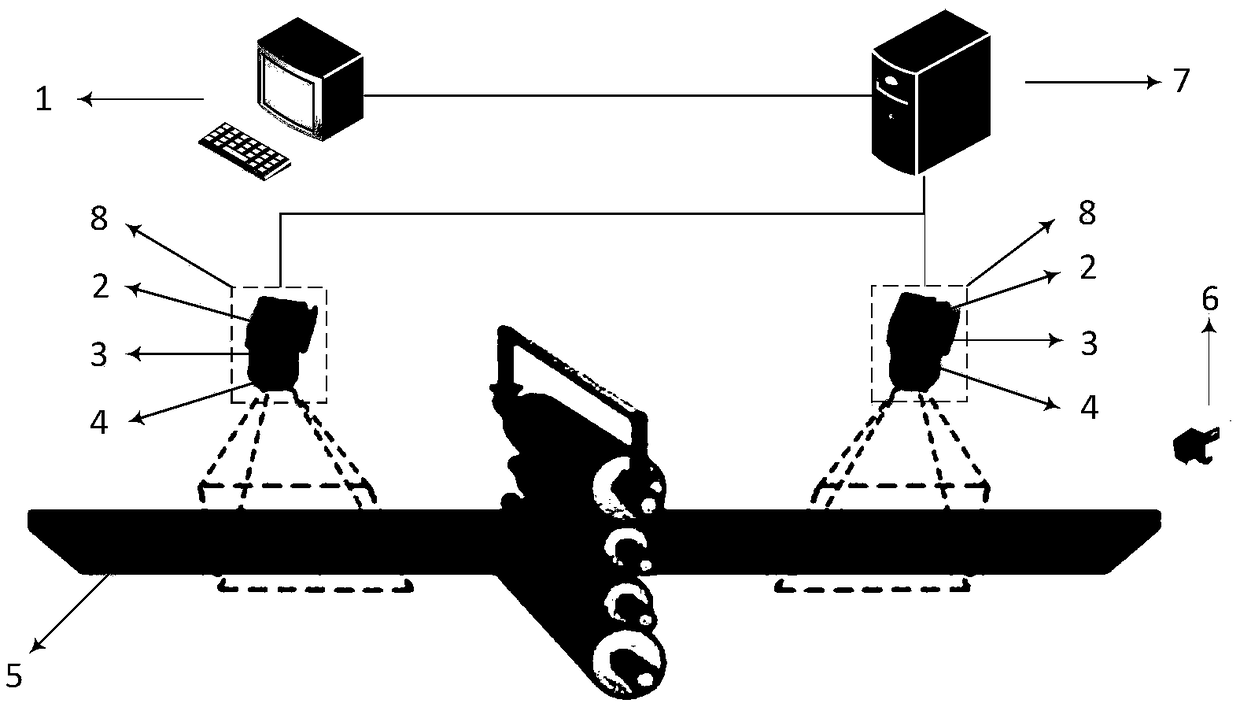
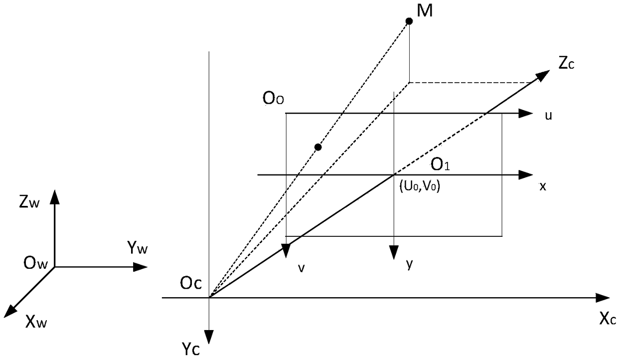
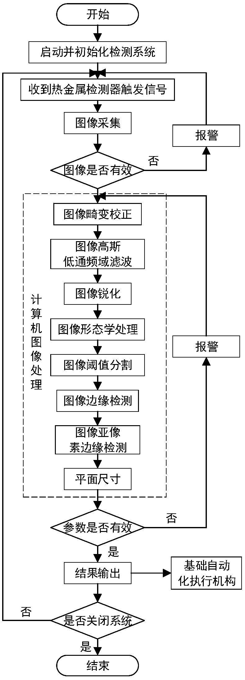
The invention particularly relates to a method for detecting the camber of plates based on machine vision, belonging to the automatic control field of steel rolling processes. The method comprises thefollowing steps: obtaining plate images through plane array CCD cameras installed right above a roller way outside of roller beds in front of and behind a rolling mill, and correcting the distortionof the images through camera calibration; performing Gaussian low-pass frequency domain filtering on the corrected images, and performing image sharpening differential operation on the filtered imagesto enhance the image boundary. Mathematical morphology transformation and threshold binarization are carried out on the images with enhanced boundaries to segment and completely extract the plate image. The pixel coordinates of the edge contour points are extracted by using the Canny edge detection operator after threshold segmentation and the sub-pixel coordinates of the plate edges are obtained by using the improved Zernike orthogonal moment sub-pixel edge detection algorithm, and the camber value is obtained by fitting.

Description

technical field [0001] The invention belongs to the field of automatic control of steel rolling process, and in particular relates to a method for detecting camber of a plate based on machine vision. Background technique [0002] In the conventional plate and strip rolling production process, due to the influence of rolling equipment and rolling process and other factors, the sickle defect of the plate often occurs. The root cause is the wedge shape of the entrance rolling piece, uneven temperature on both sides of the entrance rolling piece Asymmetric factors such as deviation, different longitudinal rigidity on both sides of the rolling mill, and roll inclination lead to asymmetrical rolling state of the rolled piece, resulting in asymmetrical longitudinal extension of each point in the transverse direction of the rolled piece, making the exit of the rolled piece at the exit section of the deformation zone The speed is asymmetrical along the lateral direction, forming a ca...

Claims


Application Information

Patent Timeline
IPC IPC(8): G06K9/34G06K9/46G06T7/13G06T7/80
CPCG06T7/13G06T7/80G06V10/267G06V10/44
Inventor 丁敬国田宝曹剑钊孙杰彭文张殿华
Owner NORTHEASTERN UNIV
Learn More