
Polarizer with printed pattern, preparation method thereof and display device

A technology for printing patterns and polarizers, which is applied in the direction of optics, polarizing elements, optical elements, etc., and can solve the problems of high production cost, defects, and low process yield

Pending Publication Date: 2019-01-11
HEFEI BOE OPTOELECTRONICS TECH +1
View PDF6 Cites 3 Cited by
  • Summary
  • Abstract
  • Description
  • Claims
  • Application Information

AI Technical Summary

Problems solved by technology

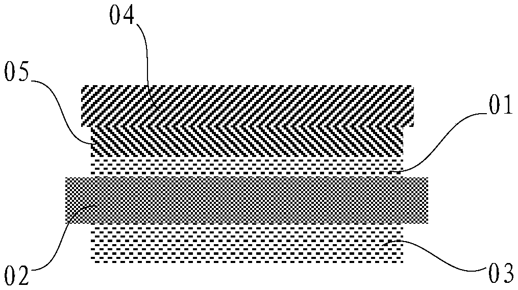
[0003] like figure 1 As shown, the existing TP-LCD includes modules such as the upper polarizer 01, the liquid crystal panel 02, and the lower polarizer 03. At present, the thickness of the panel glass of the liquid crystal panel 02 has been reduced from 0.5mm to 0.4mm, 0.3mm, 0.2 mm is even lower, and the backlight of the LCD panel 02 also adopts technologies such as composite film and ultra-thin light guide plate to reduce the thickness. strength, shading and other requirements, currently it is necessary to add cover glass 04 to the upper polarizer 01, and use optical glue 05 to bond the cover glass 04 and upper polarizer 01, but this structure will increase the cost and cost of the entire product. Thickness (cover glass 04 and optical glue 05), and for the currently popular 3D curved cover glass, because the 3D curved cover glass is not flat, traditional printing equipment cannot cope with it, and the yield rate of the new printing process is very low, making the production The cost is high. In addition, when the cover glass 04 and the upper polarizer 01 are assembled together, an assembly process is added. This assembly process is relatively complicated, which increases the probability of product failure and increases the production cost of the product.

Method used


Image

  • Polarizer with printed pattern, preparation method thereof and display device
  • Polarizer with printed pattern, preparation method thereof and display device
  • Polarizer with printed pattern, preparation method thereof and display device

Examples


Embodiment Construction

[0031] The following will clearly and completely describe the technical solutions in the embodiments of the present invention with reference to the accompanying drawings in the embodiments of the present invention. Obviously, the described embodiments are only some, not all, embodiments of the present invention. Based on the embodiments of the present invention, all other embodiments obtained by persons of ordinary skill in the art without making creative efforts belong to the protection scope of the present invention.

[0032] Such as figure 2 , image 3 , Figure 4 as well as Figure 5 As shown, a method for preparing a polarizer 1 with a printed pattern includes preparing a polarizer base material, and also includes:

[0033] Step S101, printing the ink area pattern 14 of the cover glass on the polarizer substrate and curing;

[0034] In step S102 , a protective film layer is compounded on the polarizer base material on which the ink area pattern 14 of the cover glass ...


PUM


Abstract

The invention relates to the technical field of display, and discloses a polarizer with a printing pattern, a preparation method thereof and a display device, the polarizer with printing pattern preparation method comprises the preparation of the polarizer substrate, and also comprises the following steps of: printing an ink area pattern of a cover plate glass on the polarizer substrate and curing; a high-hardness polarizer is formed by compounding a protective film layer on the polarizer substrate with the ink area pattern of the cover plate glass, an ink area pattern of the cover plate glasson the polarizer substrate is formed by printing the ink area pattern of the cover plate glass on the prepared polarizer substrate and curing, the high-hardness polarizer is formed by compounding theprotective film layer on the polarizer substrate with the ink area pattern of the cover plate glass, so that improving the hardness of the polarizer, and ensuring the optical performance and the reliability, the preparation method is simple, and the manufacturing cost is low, the polarizer manufactured through the preparation method of the polarizer with the printing pattern has the function of the cover plate glass.

Description

technical field [0001] The invention relates to the field of display technology, in particular to a polarizer with printed patterns, a preparation method thereof, and a display device. Background technique [0002] In the field of display technology, with the development of science and technology and the urgent needs of users, the thinning and thinning of display devices has become the development trend of module design, especially TP-LCD (touch liquid crystal display device) that can realize human-computer interaction. [0003] Such as figure 1 As shown, the existing TP-LCD includes modules such as the upper polarizer 01, the liquid crystal panel 02, and the lower polarizer 03. At present, the thickness of the panel glass of the liquid crystal panel 02 has been reduced from 0.5mm to 0.4mm, 0.3mm, 0.2 mm is even lower, and the backlight of the LCD panel 02 also adopts technologies such as composite film and ultra-thin light guide plate to reduce the thickness. strength, sh...

Claims


Application Information

Patent Timeline
IPC IPC(8): G02B5/30G02B1/14G02F1/1335
CPCG02B1/14G02B5/305G02F1/133528
Inventor 郑彪李虎赵雪梅
Owner HEFEI BOE OPTOELECTRONICS TECH
Learn More