Gas-liquid double-kinetic-energy negative pressure injection and suction device

A negative pressure, gas-liquid technology, applied in the field of gas-liquid dual kinetic energy negative pressure jet suction device, can solve the problems of uneven stirring, operator injury, pollution of the environment, etc., and achieve the effect of improving the injection effect and uniform distribution of the medicine

Active Publication Date: 2019-01-11
福州思琪科技有限公司
View PDF5 Cites 1 Cited by
  • Summary
  • Abstract
  • Description
  • Claims
  • Application Information

AI Technical Summary

Problems solved by technology

[0002] In the process of oil extraction, due to the complex geological structure, it is necessary to inject some chemicals into the formation to increase oil production. Added chemicals such as: cross-linking agent, foaming agent, water shutoff agent, plugging agent, expansion agent, etc., these Some pharmaceutical materials are in the form of flocculents and tiny particles, most of which are harmful to the human body; in addition, some are viscous, and some are in the form of solid particles; The uniform addition method
At present, a mixer is generally used to stir, and the pressure pump is used to inject it into the corresponding position of the formation along the injection pipeline. The existing problems are: first, the mixing is not uniform, which is easy to cause blockage to the pipeline; second, the flocs are easy to float and pollute the environment; The 3rd, most injected medicaments are poisonous, easily cause bodily injury to operator;
The problem is that only the high-pressure liquid passes through the nozzle to generate negative pressure, and the medicine that needs to be added is sucked away. The self-absorption ability is limited, and the medicine in the form of flocculent and tiny particles can meet the requirements. However, when encountering solid granular liquid of the medicament, there is no ability to suck it into the injection line, so the device has certain limitations in use

Method used


Image

  • Gas-liquid double-kinetic-energy negative pressure injection and suction device
  • Gas-liquid double-kinetic-energy negative pressure injection and suction device
  • Gas-liquid double-kinetic-energy negative pressure injection and suction device

Examples


Embodiment Construction

[0018] The preferred embodiments of the present invention will be described below in conjunction with the accompanying drawings. It should be understood that the preferred embodiments described here are only used to illustrate and explain the present invention, and are not intended to limit the present invention.

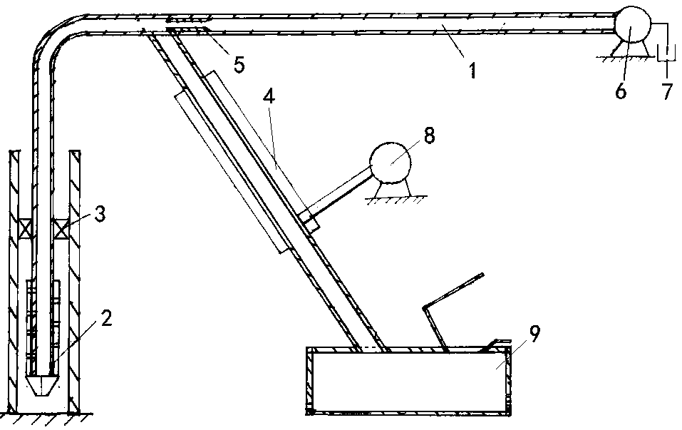
[0019] Refer to attached figure 1 , a gas-liquid dual kinetic energy negative pressure injection device mentioned in the present invention, its technical solution is: comprising coiled tubing 1, formation rotating nozzle 2, packer 3, tornado generator 4, jet directional device 5, high pressure pump 6. Liquid supply pool 7, air compressor 8, one end of the coiled tubing 1 is connected to the rotary nozzle 2 of the formation and installed in the casing under the formation, the other end of the coiled tubing 1 is connected to the high-pressure pump 6 on the ground, and the high-pressure pump 6. Inject the liquid from the liquid supply pool 7 on the ground into the form...


PUM


Abstract

The invention relates to a gas-liquid double-kinetic-energy negative pressure injection and suction device. The technical scheme is that one end of a coiled tubing is connected with a formation rotarynozzle, the other end is connected with a high-pressure pump on the ground, a liquid in a liquid supply pool on the ground is injected into the formation via the coiled tubing through the high-pressure pump, the middle part of the coiled tubing is provided with an injection orientator, the speed of the passing liquid is further improved so as to form a negative pressure chamber, the negative pressure chamber is connected with the upper end of a tornado generator through a negative pressure injection and suction pipe, the lower end of the tornado generator is connected with a feeding box through the negative pressure injection and suction pipe, and the lower side of the tornado generator is connected with an air compressor. The beneficial effects are that the negative pressure chamber of the coiled tubing is connected with the tornado generator, and the tornado generated by the tornado generator is high in suction, so that granular medicaments are driven to be conveyed upward along thenegative pressure injection and suction device, gas-liquid double-kinetic-energy negative pressure injection and suction are realized, and the conveying problem of most medicaments is solved; and theinjection effect is improved, and thus the formation repair work is further quickly completed.

Description

technical field [0001] The invention relates to an oil exploitation process device and method, in particular to a gas-liquid double kinetic energy negative pressure injection device. Background technique [0002] In the process of oil extraction, due to the complex geological structure, it is necessary to inject some chemicals into the formation to increase oil production. Added chemicals such as: cross-linking agent, foaming agent, water shutoff agent, plugging agent, expansion agent, etc., these Some pharmaceutical materials are in the form of flocculents and tiny particles, most of which are harmful to the human body; in addition, some are viscous, and some are in the form of solid particles; , uniform addition method. At present, a mixer is generally used to stir, and the pressure pump is used to inject it into the corresponding position of the formation along the injection pipeline. The existing problems are: first, the mixing is not uniform, which is easy to cause blo...

Claims


Application Information

Patent Timeline
Patent Type & Authority Applications(China)
IPC IPC(8): E21B43/16B65G53/24
CPCB65G53/24E21B43/16
Inventor 刘森瑞刘岩
Owner 福州思琪科技有限公司
Why Eureka
Try Eureka