A casting device for cylinder liner molding

A cylinder liner and frame technology, applied in the field of cylinder liner molding casting devices, can solve the problems of low production efficiency and long waiting time, achieve the effect of continuous cooling, reduce waiting time, and improve production efficiency

Active Publication Date: 2021-09-28
ANHUI PROVINCE YUEXI CYLINDER
View PDF0 Cites 0 Cited by
  • Summary
  • Abstract
  • Description
  • Claims
  • Application Information

AI Technical Summary

Problems solved by technology

However, it is difficult to take out the materials in this way, resulting in longer waiting time and lower production efficiency

Method used


Image

  • A casting device for cylinder liner molding
  • A casting device for cylinder liner molding
  • A casting device for cylinder liner molding

Examples


Embodiment 1

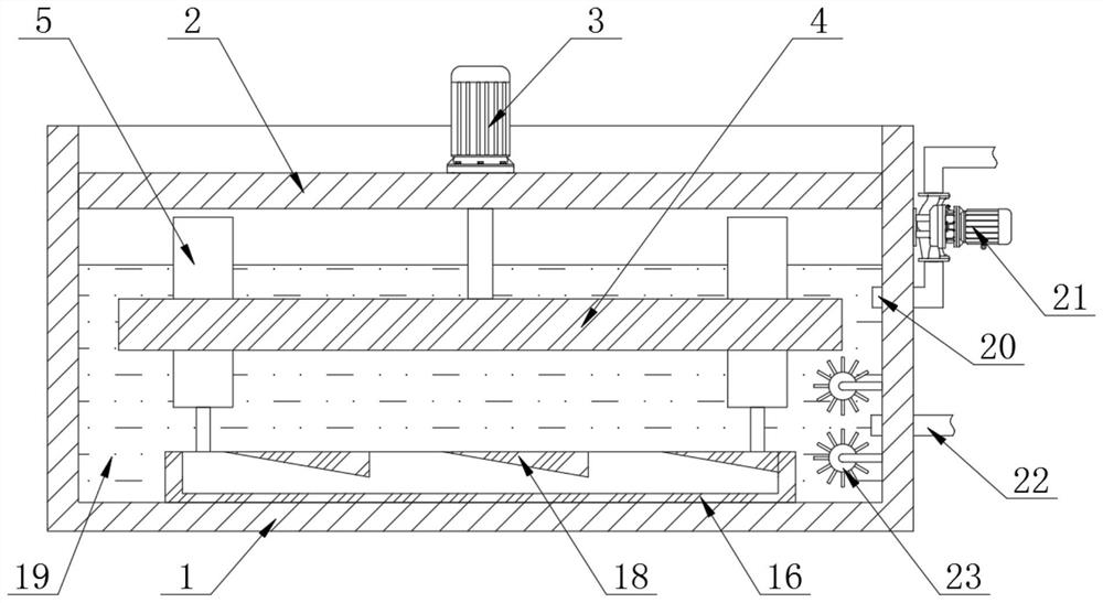
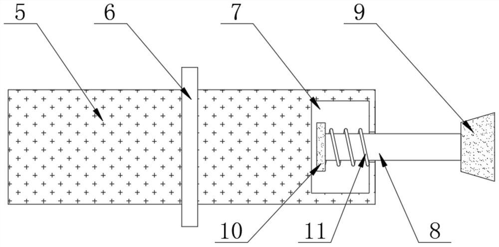
[0024] according to Figure 1-5 The shown casting device for cylinder liner molding includes a frame 1, the top of the frame 1 is provided with a connecting plate 2, the top of the connecting plate 2 is provided with a transmission motor 3, and the output shaft of the transmission motor 3 is One end is provided with a drive plate 4, the interior of the drive plate 4 is provided with a pouring mold body 5, the outer wall of the pouring mold body 5 is provided with a positioning block 6, and one end of the pouring mold body 5 is provided with a receiving cavity 7. A connecting rod 8 is provided inside the receiving cavity 7, a slider 9 is provided at one end of the connecting rod 8, and a knocking block 10 is provided at the other end of the connecting rod 8, and a connection between the knocking block 10 and the inner wall of the receiving cavity 7 is provided. A telescopic spring 11 is arranged between them, and a through groove 12 is provided at the connection between the dri...

Embodiment 2

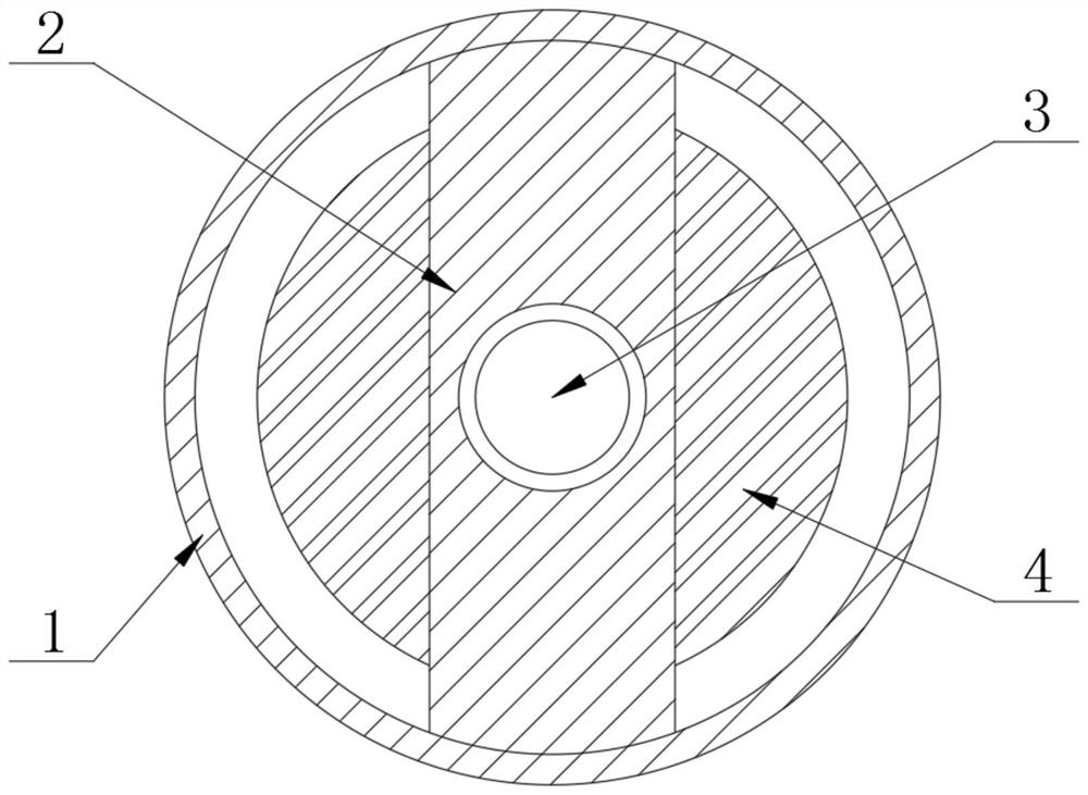
[0031] according to figure 2 As shown in a casting device for cylinder liner molding, the inner cavity of the frame 1 is provided with cooling water 19, the height of the cooling water 19 is lower than the top position of the pouring mold body 5, and the cooling water 19 is opposite to the pouring mold body 5 When the castings inside are cooling down, the temperature of the cooling water 19 is gradually warming up;

[0032] One side of the frame 1 is provided with a water outlet pipe 20, the water delivery pipe is provided with a water pump 21, the water pump 21 is arranged on the outer wall of the frame 1, the bottom of the water outlet pipe 20 is provided with a water inlet pipe 22, and the cooling water 19 is provided according to When the temperature is higher, the density is lower. The heated cooling water 19 is drawn from the rack 1 by the outlet pipe 20 at the top under the action of the water pump 21, and is discharged to the inside of the external cooling pool for co...


PUM


Abstract

The invention discloses a casting device for cylinder liner molding, which comprises a frame, a connecting plate is arranged on the top of the frame, a transmission motor is arranged on the top of the connecting plate, and a drive plate is arranged at one end of the output shaft of the transmission motor , the inside of the drive plate is provided with a pouring mold body, the outer wall of the pouring mold body is provided with a positioning block, one end of the pouring mold body is provided with a storage cavity, and a connecting rod is provided inside the storage cavity. One end of the rod is provided with a slider. The present invention utilizes the sliding of the slider inside the chute and the positioning of the limit bar, and the drive motor drives the drive plate to rotate in the frame. The limit is driven by the connecting rod to shrink the telescopic spring. After the slider is separated from the limit bar, under the action of the rebound force of the telescopic spring, the connecting rod drives the knocking block to hit the inner wall of the storage cavity, so that the molded parts are better Separation from the pouring mold body.

Description

technical field [0001] The invention relates to the technical field of cylinder liner production and casting equipment, in particular to a casting device for forming a cylinder liner. Background technique [0002] The cylinder liner is the abbreviation of the cylinder liner. It is embedded in the cylinder barrel of the cylinder block and forms the combustion chamber together with the piston and the cylinder head. The cylinder liner is divided into two categories: dry cylinder liner and wet cylinder liner. The cylinder liner whose back side does not contact the cooling water is called a dry cylinder liner, and the cylinder liner whose back side is in contact with cooling water is a wet cylinder liner. The dry cylinder liner has a thinner thickness, simple structure and convenient processing. The wet cylinder liner is in direct contact with the cooling water, so it is beneficial to the cooling of the engine, and is conducive to the miniaturization and weight reduction of the ...

Claims


Application Information

Patent Timeline
Patent Type & Authority Patents(China)
IPC IPC(8): B22D35/04B22D29/00B22D27/04
CPCB22D27/04B22D29/00B22D35/04
Inventor 周国荣
Owner ANHUI PROVINCE YUEXI CYLINDER
Why Eureka
Try Eureka