
Machining system for downward core pulling casting piston

A processing system and piston technology, applied in metal processing equipment, casting molds, cores, etc., can solve the problems of guide rod clearance error, high product scrap rate, difficult temperature control, etc., to improve the positioning accuracy of the guide and improve the internal purity , Reduce the effect of shrinkage cavity shrinkage

Inactive Publication Date: 2019-01-11
ANHUI HIGH TECH POWER TECH
View PDF6 Cites 0 Cited by
  • Summary
  • Abstract
  • Description
  • Claims
  • Application Information

AI Technical Summary

Problems solved by technology

[0003] However, this processing system is still immature, and it is easy to process defective products. The main manifestation is that the temperature is not easy to control during the cooling and forming process of the piston in the mold, which directly leads to the macroscopic failure of the internal structure of the piston after forming, and even the failure to form it completely. The guide positioning accuracy of the blank during the finishing process is not high. The traditional six-point positioning is actually an under-positioning method, because there are cumulative errors in the sleeve clearance error of the guide rod and the draft angle error between the blank hole and the guide. The result is that after the rough boring of the aluminum piston, the symmetry error of the pin hole is unstable, the deflection of the two holes is unstable, and the diagonal line is in a state, the product shape and position tolerance accuracy is unstable, and the product scrap rate is high.

Method used


Image

  • Machining system for downward core pulling casting piston
  • Machining system for downward core pulling casting piston
  • Machining system for downward core pulling casting piston

Examples


Embodiment

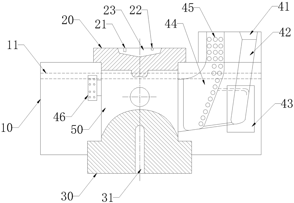
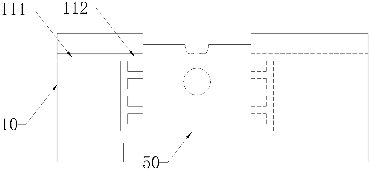
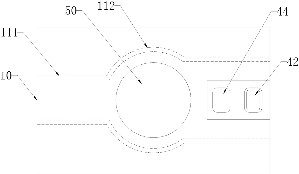
[0035] Such as Figures 1 to 9 As shown, a processing system for a lower core-pulling casting piston includes a blank processing device and a finishing device, the blank processing device includes a mold set for machining and forming a piston blank, and the mold set includes a metal outer mold 10, a metal top mold 20 and a metal inner mold 30, the lower end of the metal top mold 20 is embedded in the upper part of the metal outer mold 10, the upper end is higher than the upper plane of the metal outer mold 10, and the upper end of the metal inner mold 30 is embedded in the metal outer mold 10, and the lower end is lower than the lower plane of the metal outer mold 10, the forming cavity 50 of the piston is formed between the metal outer mold 10, the metal top mold 20 and the metal inner mold 30; the finishing device includes a fixing device, The pressing device, the guiding and positioning device and the processing knife 60 are fixedly installed on the fixing device, and the p...


PUM


Abstract

The invention discloses a machining system for a downward core pulling casting piston. The system comprises a blank machining device and a finish machining device. The blank machining device comprisesa mold group comprising a metal outer mold, a metal top mold and a metal inner mold, the lower end of the metal top mold is embedded in the upper part of the metal outer mold, the upper end of the metal inner mold is embedded in the lower end of the metal outer mold, and a molding cavity of a piston is formed among the metal outer mold, the metal top mold and the metal inner mold. The finish machining device comprises a fixing device, a pressing device, a guiding and positioning device and machining knifes, the pressing device and the guiding and positioning device are fixedly installed on the fixing device, and the machining knifes are symmetrically arranged on opposite sides of the fixing device. According to the machining system, the pouring molding of the piston blank is ensured through a cooling system arranged in the blank machining device and the guiding and positioning device in the finish machining device, the positioning accuracy of the finish machining process is improved,and thus the product scrap rate of the downward core pulling casting piston is reduced and the production efficiency of the product is improved.

Description

technical field [0001] The invention relates to the technical field of piston processing, in particular to a processing system for lower core-pulling casting pistons. Background technique [0002] The existing piston production generally adopts the metal mold gravity casting method. With the maturity of domestic casting machine technology, the original manual core-pulling structure metal mold production method has been gradually eliminated by the mechanical core-pulling structure metal mold production. Now a kind of processing method of piston is to process the piston blank with combustion chamber through the lower core-pulling die, and then carry out finishing machining with a lathe to obtain the finished piston. [0003] However, this processing system is still immature, and it is easy to process defective products. The main manifestation is that the temperature is not easy to control during the cooling and forming process of the piston in the mold, which directly leads to...

Claims


Application Information

Patent Timeline
IPC IPC(8): B22C9/06B22C9/08B22C9/22B23P23/04
CPCB22C9/065B22C9/082B22C9/086B22C9/088B22C9/22B23P23/04
Inventor 蓝天章高伟余明董学林曹海滨
Owner ANHUI HIGH TECH POWER TECH
Learn More