
Air-coupled capacitive micromachined ultrasonic transducer with T-shaped cavity structure and preparation method thereof

An air-coupling and cavity technology, applied in the field of MEMS and ultrasonic transducers, can solve the problems of reducing the consistency of the unit structure in the array, limiting the maximum vibration displacement space of the membrane, and complex membrane structure design, so as to improve the output sound pressure and Receiving sensitivity, increasing electromechanical coupling coefficient and receiving sensitivity, good structure and performance consistency

Active Publication Date: 2019-01-11
XI AN JIAOTONG UNIV
View PDF5 Cites 8 Cited by
  • Summary
  • Abstract
  • Description
  • Claims
  • Application Information

AI Technical Summary

Problems solved by technology

However, the current conventional air-coupled CMUT needs to be loaded with a high DC bias voltage (>100V) to obtain a high electromechanical coupling coefficient, and the average displacement of the film is mainly increased by the design of the film structure to increase the output sound pressure. This method leads to The thin film structure design is complex, which increases the difficulty of the process and reduces the consistency of the unit structure in the array
In addition, for a certain cavity height, the complex membrane structure also limits the maximum vibration displacement space of the membrane, resulting in limited improvement of the transmission and reception performance (currently, the highest transmission sensitivity of CMUT is 34Pa / V, and the highest reception sensitivity is 17mV / Pa )
Therefore, the existing air-coupled CMUTs do not comprehensively consider factors such as operating voltage, manufacturing process, and transmitting and receiving performance.

Method used


Image

  • Air-coupled capacitive micromachined ultrasonic transducer with T-shaped cavity structure and preparation method thereof
  • Air-coupled capacitive micromachined ultrasonic transducer with T-shaped cavity structure and preparation method thereof
  • Air-coupled capacitive micromachined ultrasonic transducer with T-shaped cavity structure and preparation method thereof

Examples


Embodiment Construction

[0032] The present invention is described in detail below in conjunction with accompanying drawing and embodiment:

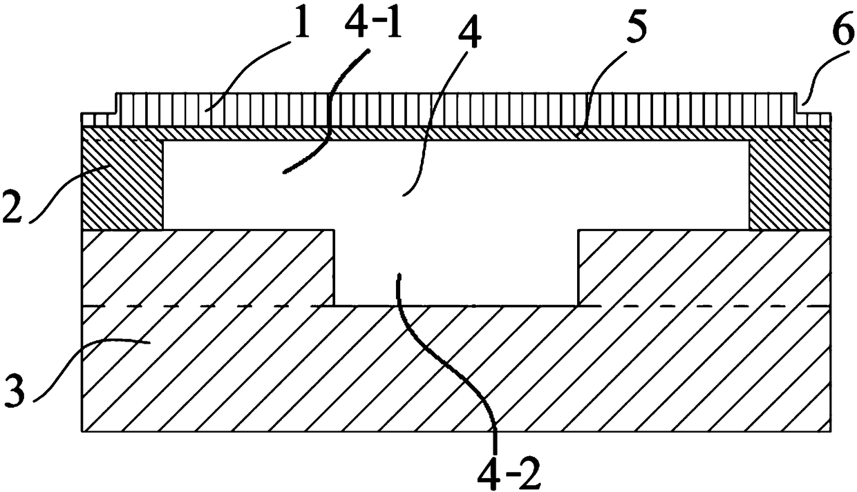
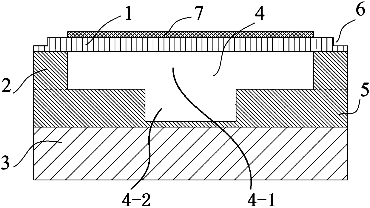
[0033] Such as figure 1 As shown, the air-coupled CMUT with a T-shaped cavity structure of the present invention includes a vibrating film 1, a pillar 2, a lower electrode 3, a T-shaped cavity 4, an insulating layer 5, and an upper electrode 7, wherein the T-shaped cavity 4 refers to: The longitudinal section of the cavity along its axial direction is T-shaped; the cross-sectional shape of the T-shaped cavity 4 can be a circle or a regular polygon;

[0034]The upper half of the T-shaped cavity 4 runs through the pillar 2 along the thickness direction of the pillar 2; the lower electrode 3 is made of low-resistance silicon wafer or other low-resistance materials, and a groove is opened in the central area of ​​the upper surface, and the groove forms a T-shaped cavity. The lower part of 4; the shape of the upper part of the T-shaped cavity 4 is consistent with th...


PUM


Abstract

The invention discloses an air-coupled capacitive micromachined ultrasonic transducer with a T-shaped cavity structure and a preparation method thereof. Annular stress relief grooves are formed in theareas, fixed to the surfaces of supporting columns, of a vibration thin film. A cavity of the air-coupled capacitive micromachined ultrasonic transducer is T-shaped, that is, the electrode distance between upper and lower electrodes in the central region of the cavity is greater than the electrode distance between upper and lower electrodes of the region, close to the supporting columns, on the periphery of the cavity. According to the air-coupled capacitive micromachined ultrasonic transducer with the T-shaped cavity structure and the preparation method thereof, design of the T-shaped cavityis used for reducing the electrode distance between the upper and lower electrodes in the area on the periphery of the cavity, thus the average displacement of the thin film can be increased withoutaffecting the maximum amplitude of the thin film, then the output sound pressure is increased, and the electromechanical coupling coefficient and receiving sensitivity are improved; in addition, the method of forming stress relief grooves in the fixing end of the thin film can further reduce constraint of the fixing area on deformation of the thin film, deformation of the thin film is increased and the output sound pressure is improved.

Description

technical field [0001] The invention relates to MEMS and ultrasonic transducer technologies, in particular to an air-coupled CMUT with a T-shaped cavity structure and a preparation method thereof facing the field of air-coupled applications. Background technique [0002] Ultrasonic transducers are used for transmitting and receiving ultrasonic waves, and are the core devices for realizing ultrasonic testing technology. Due to the characteristics of high frequency, good propagation direction, concentrated energy, strong penetrating power, no noise pollution, and cavitation phenomenon in liquid, ultrasonic transducers are widely used in medical and health, industrial non-destructive testing, chemical production, marine It has important application value in fields such as terrain exploration and military sonar. Traditional piezoelectric ultrasonic transducers have been unable to meet the increasing technical requirements of various engineering applications due to technical pro...

Claims


Application Information

Patent Timeline
Patent Type & Authority Applications(China)
IPC IPC(8): B06B1/02B81B7/02
CPCB06B1/02B81B7/02
Inventor 李支康赵立波赵一鹤李杰徐廷中罗国希郭帅帅蒋庄德
Owner XI AN JIAOTONG UNIV
Learn More