Battery Fixture

A battery clamp and clamp base technology, which is used in secondary battery manufacturing, climate sustainability, and final product manufacturing, etc., can solve problems such as easy lifting of clamp arms, incomplete contact between clamps and tabs, and impact on test results. , to prevent the chuck from lifting

Active Publication Date: 2020-09-15
REPOWER TECH CO LTD
View PDF6 Cites 0 Cited by
  • Summary
  • Abstract
  • Description
  • Claims
  • Application Information

AI Technical Summary

Problems solved by technology

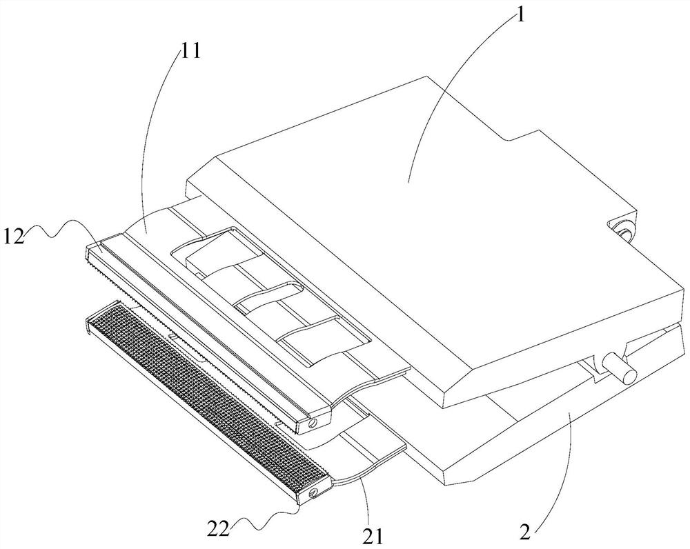
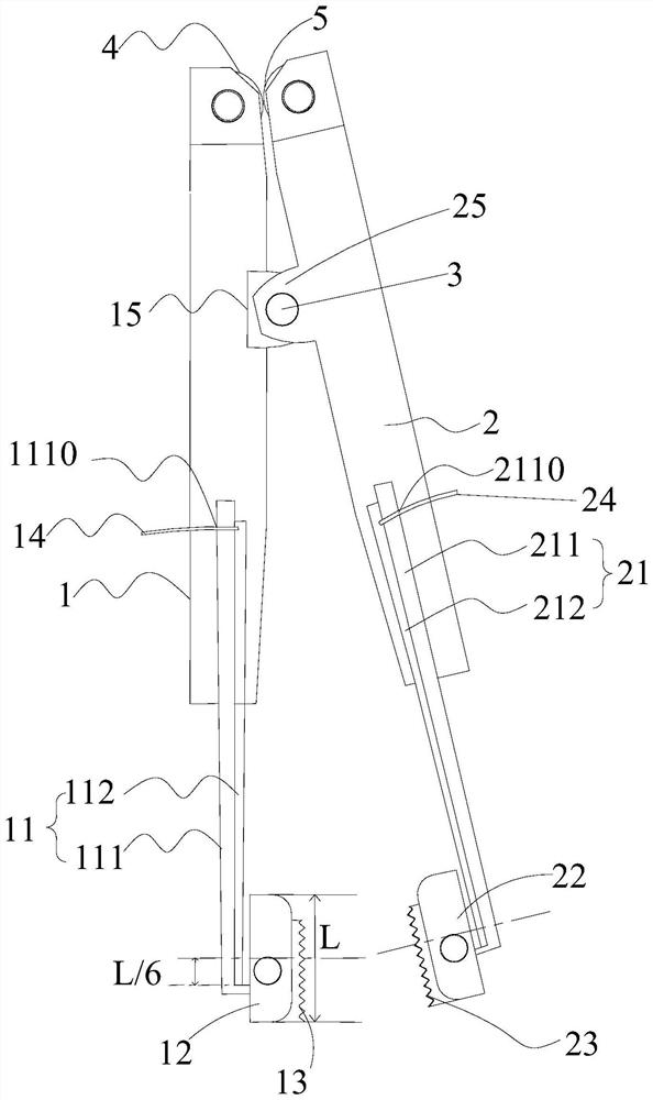
[0004] The purpose of the present invention is to provide a battery clamping device, aiming to solve the technical problem in the prior art that the clamping arm of the battery clamping device is easily tilted during use, so that the chuck and the tab cannot be fully contacted, thereby affecting the test effect

Method used


Image

  • Battery Fixture
  • Battery Fixture

Examples


Embodiment Construction

[0025] In order to make the object, technical solution and advantages of the present invention clearer, the present invention will be further described in detail below in conjunction with the accompanying drawings and embodiments. It should be understood that the specific embodiments described here are only used to explain the present invention, not to limit the present invention.

[0026] It should be noted that when an element is referred to as being “fixed on” or “disposed on” another element, it may be directly on the other element or there may be an intervening element at the same time. When an element is referred to as being "connected to" another element, it can be directly connected to the other element or intervening elements may also be present.

[0027] In addition, it should be noted that the orientation terms such as left, right, up, and down in the embodiments of the present invention are only relative concepts or refer to the normal use state of the product, and...


PUM


Abstract

The invention belongs to the technical field of clamping devices, and discloses a battery clamping device, which includes a first clamping seat and a second clamping seat correspondingly arranged, and a hinge mechanism. The front end of the first clamping seat is provided with a first rigid clamping arm, The front end of the second clamp seat is provided with a second rigid clamp arm, the free end of the first rigid clamp arm is provided with a first clamp, and the free end of the second rigid clamp arm is provided with a second clamp, the first rigid clamp arm is provided with a second clamp. A connection point between a rigid clamp arm and the first clamp forms a first preset distance from the center of the first clamp, and a connection point between the second rigid clamp arm and the second clamp is at a distance from the center of the second clamp. A second preset distance is formed at the position. When the first clamping seat and the second clamping seat receive the extrusion force, because the above-mentioned clamping arm is rigid, it is ensured that the clamping arm itself will not warp during the stress process; and because the rigidity The connection point between the arm and the collet deviates from the center of the collet by a preset distance, at this time, the clamp arm generates a biasing force on the collet, which makes it difficult to rotate the collet and prevents the collet from tilting.

Description

technical field [0001] The invention belongs to the field of clamp devices, and more specifically relates to a battery clamp device. Background technique [0002] In the process of battery production or use, it is necessary to perform some process or performance tests on the battery. At this time, it is necessary to set up a fixture device for conductive use. [0003] However, for the existing polymer soft-packed power batteries, it is necessary to derive a large current from the tabs, so the tab fixtures of this type of battery are mostly made of copper skin, but because the copper skin material itself is relatively soft, the clamp device provides When the pressure forces the jig to clamp the lug, the jig arm of the jig is easy to tilt, so that the chuck and the lug cannot be fully contacted, resulting in poor contact, which affects the test effect. Contents of the invention [0004] The object of the present invention is to provide a battery clamping device, aiming to s...

Claims


Application Information

Patent Timeline
Patent Type & Authority Patents(China)
IPC IPC(8): H01M10/04
CPCH01M10/04Y02P70/50
Inventor 毛广甫
Owner REPOWER TECH CO LTD
Why Eureka
Try Eureka