
A permanent magnet circuit system for a relativistic magnetron

A technology of relativistic magnetron and magnetic circuit system, which is applied in the field of permanent magnet magnetic circuit system for relativistic magnetron, can solve the problems of ineffective gathering of magnetic field, increase of permanent magnet usage, multiple stray magnetic fields, etc., and meet the requirements of High-power microwave output, improved uniformity, and a large range of magnetic field uniformity

Active Publication Date: 2019-01-08
CENT IRON & STEEL RES INST
View PDF4 Cites 2 Cited by
  • Summary
  • Abstract
  • Description
  • Claims
  • Application Information

AI Technical Summary

Problems solved by technology

However, the magnetic force lines generated by the permanent magnets outside the magnetron are conducted through the air, which will cause more flux leakage; the ring design with embedded permanent magnets cannot effectively gather the magnetic field, which will generate more stray magnetic field
In order to meet the magnetic field strength requirements in the working area, the use of permanent magnets must be increased, which will limit the miniaturization of the equipment

Method used


Image

  • A permanent magnet circuit system for a relativistic magnetron
  • A permanent magnet circuit system for a relativistic magnetron
  • A permanent magnet circuit system for a relativistic magnetron

Examples


Embodiment 1

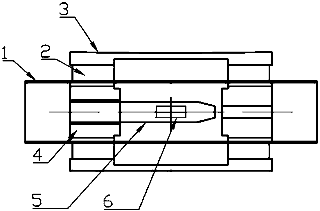
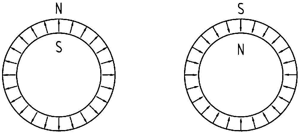
[0034] The sintered NdFeB permanent magnet with the brand name N50 on the market is selected to be processed into a tile-shaped magnet. The main magnetic indicators of the permanent magnet are: Br=14.0-14.6kGs, bHc≥11kOe, jHc≥12kOe, (BH)max=48-51MGOe . After the tile-shaped permanent magnet is magnetized, it is bonded into a radial permanent magnet ring 2, and the magnetization direction is as follows: figure 2 As shown, the magnetization direction of one radially oriented permanent magnet ring 2 is the outer S inner N pole, and the magnetization direction of the other radially oriented permanent magnet ring 2 is the outer N inner S pole. The inner diameter of the two radially oriented permanent magnet rings 2 is 200mm, the outer diameter is 320mm, and the thickness is 70mm. The outer diameter of the yoke 3 is 360 mm, and the length is 350 mm. Magnetic gathering boot 4 selects electrician pure iron material for use, and its shape is image 3 As shown in (a), the dimensions...

Embodiment 2

[0041] The same radially oriented permanent magnet ring 2 and yoke 3 as in Example 1 were fabricated. The magnetic pole piece 4 adopts the combination of soft magnetism and permanent magnetism, and its structure is as follows: image 3 (b) shown. The soft magnetic part of the magnetic gathering pole piece 4 is made of electric pure iron material, and the permanent magnetic part is made of N50 sintered NdFeB material. The structural dimensions of the magnetic pole piece 4 are: a=190mm, b=180mm, c1=85mm, c2=10mm, h=70mm, H=85mm. The magnetization direction of the permanent magnet of the magnetic pole piece 4 is along the horizontal direction, and the magnetization direction is as image 3 (b) shown.

[0042]After the assembly is completed, use a gauss meter to measure the magnetic field at different positions in the axial and radial directions of the working area 6. The actual measured axial magnetic field range of the working area 6 along the axial direction is 253-257mT, an...


PUM

PropertyMeasurementUnit
Length rangeaaaaaaaaaa
The inside diameter ofaaaaaaaaaa
Outer diameteraaaaaaaaaa

Abstract

The invention relates to the technical field of high-power microwave, in particular to a permanent magnet magnetic circuit system for relativistic magnetron. The magnetic circuit system comprises an anode cylinder (1), an external magnetic circuit and an internal magnetic circuit. The outer magnetic circuit comprises two radially oriented permanent rings (2) and a yoke (3) connecting the two radially oriented permanent rings (2), and the inner magnetic circuit comprises two magnetic collecting pole shoes (4). The outer magnetic circuit is located outside the anode cylinder (1) and the inner magnetic circuit is located inside the anode cylinder (1). The structure of the external magnetic circuit and the internal magnetic circuit designed by the invention can effectively reduce the leakage magnetic field and improve the uniformity of the axial magnetic field in the working area of the relativistic magnetron. The invention can effectively reduce the overall weight of the magnetic circuitsystem. The permanent magnet magnetic circuit system of the invention can stably provide the relativistic magnetron with good uniformity of the working magnetic field for a long time, and can satisfythe high-power microwave output when the relativistic magnetron is working.

Description

technical field [0001] The invention relates to the technical field of high-power microwaves, in particular to a permanent magnet magnetic circuit system for a relativistic magnetron. Background technique [0002] The working principle of the high-power microwave source device is to use the interaction between the electron beam and the microwave cavity to generate high-power microwave output, and the transmission of the electron beam is confined and controlled by an external magnetic field. It is mainly used in national defense and military fields such as high-power microwave weapons, high-power radars, shock radars, and super jammers. [0003] Relativistic magnetron (RM) is currently one of the most efficient high-power microwave sources. Because of its advantages such as simple structure, firmness and high working reliability, it has attracted widespread attention. One of the current research focuses is to improve the overall energy efficiency of relativistic magnetrons ...

Claims


Application Information

Patent Timeline
IPC IPC(8): H01J23/087H01J25/50
CPCH01J23/087H01J25/50
Inventor 徐吉元董生智陈红升韩瑞李冬丽方以坤李卫
Owner CENT IRON & STEEL RES INST
Learn More