
Grooving-chamfering machining process for automobile brake pad, and special grooving-chamfering combined machine

A processing technology and a technology for brake pads, applied in the field of slotting and chamfering combined machines, can solve the problems of low automation level, inconvenient first installation, easy to shake, etc. Position controllable and precise effect

Pending Publication Date: 2019-01-08
晋江市凯燕新材料研究院股份有限公司
View PDF1 Cites 2 Cited by
  • Summary
  • Abstract
  • Description
  • Claims
  • Application Information

AI Technical Summary

Problems solved by technology

However, in this technical solution, since the brake pad is installed on the limit mounting plate, the first installation is inconvenient and it is easy to shake during the chamfering or grooving process, and the second brake pad must have at least one end edge and a limit position. The mounting plates are in contact, so it needs to be disassembled and reinstalled for double-sided chamfering or slotting, and the processing accuracy and consistency are difficult to guarantee, and the automation level is low.

Method used


Image

  • Grooving-chamfering machining process for automobile brake pad, and special grooving-chamfering combined machine
  • Grooving-chamfering machining process for automobile brake pad, and special grooving-chamfering combined machine
  • Grooving-chamfering machining process for automobile brake pad, and special grooving-chamfering combined machine

Examples


Embodiment Construction

[0035] The present invention will be further described below in conjunction with accompanying drawing:

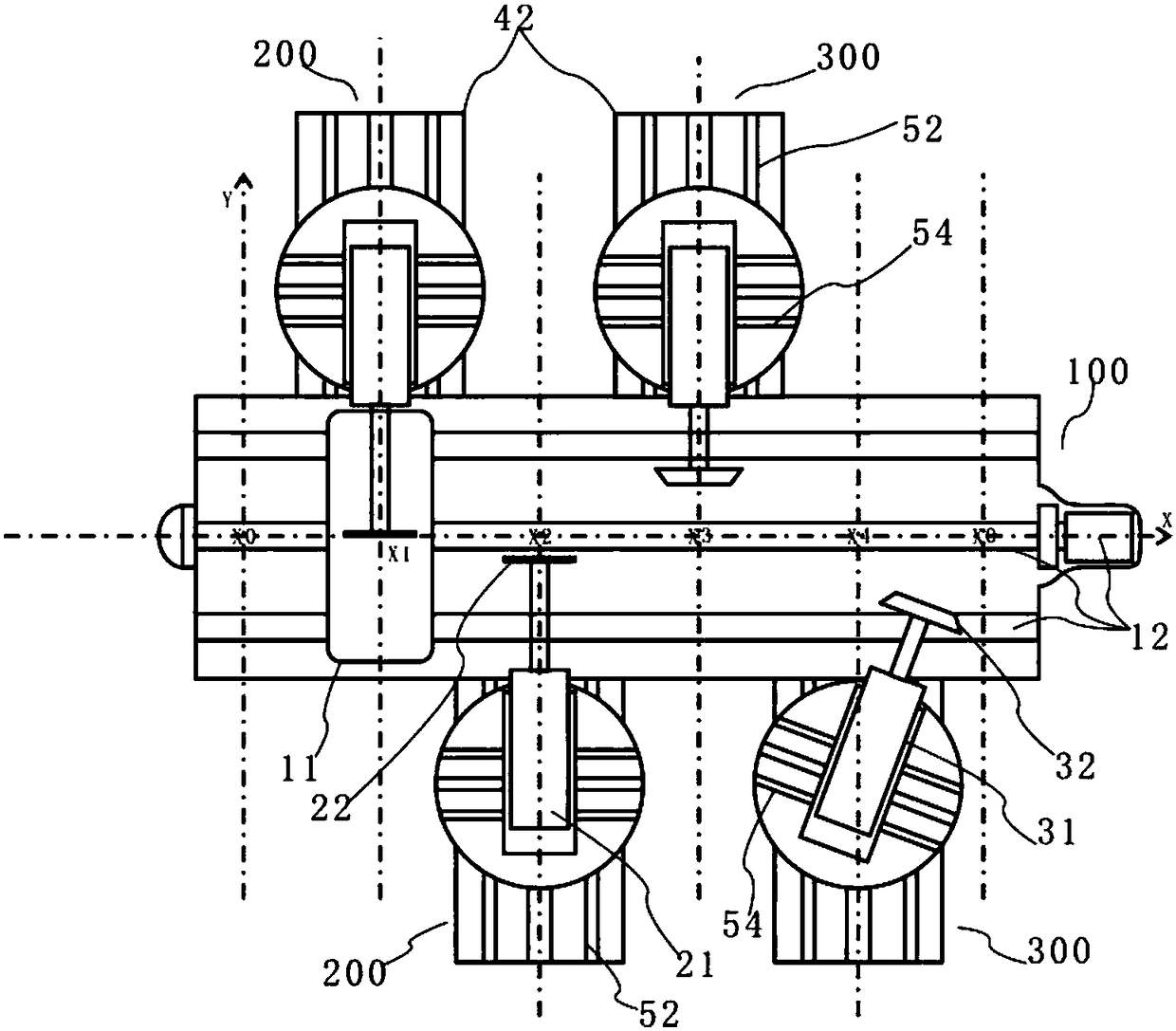
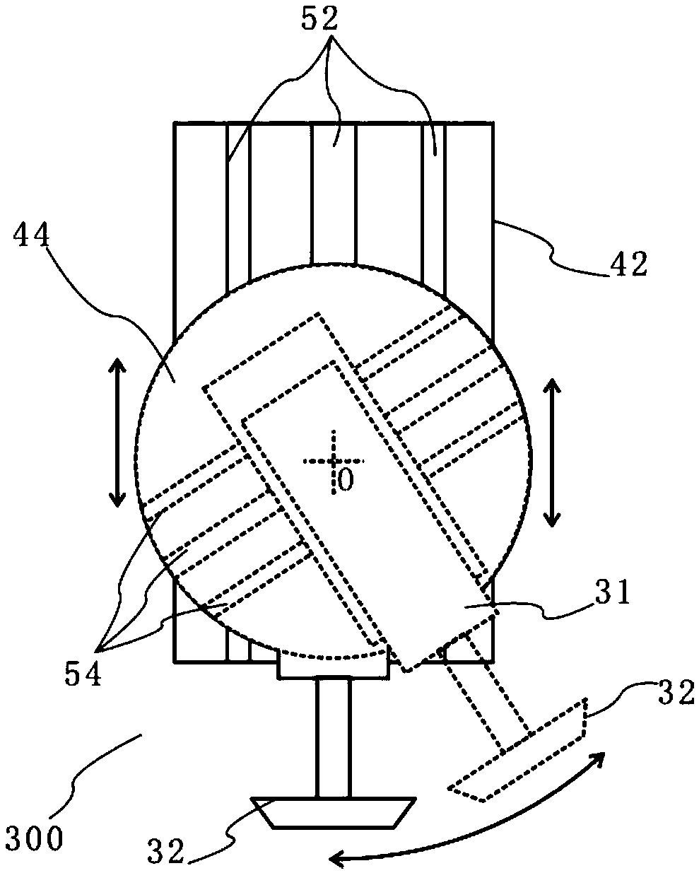
[0036] Such as Figure 1-5As shown, the present embodiment provides a slotting and chamfering combination machine for automobile brake pads, including a feeder mechanism 100 and functional units respectively arranged on both sides of the feeder mechanism 100 perpendicular to the feeder direction. The functional units described above include a slotting unit 200 and a chamfering unit 300. The slotting and chamfering combination machine is used for slotting and chamfering processing of automobile brake pads, wherein the slotting form includes but is not limited to Straight grooves parallel to the central axis of X and inclined grooves whose axis is inclined relative to the X central axis of the automobile brake pad. The chamfering of the hypotenuse with an included angle with respect to the X central axis of the automobile brake pad.

[0037] In this embodiment, the delivery...


PUM


Abstract

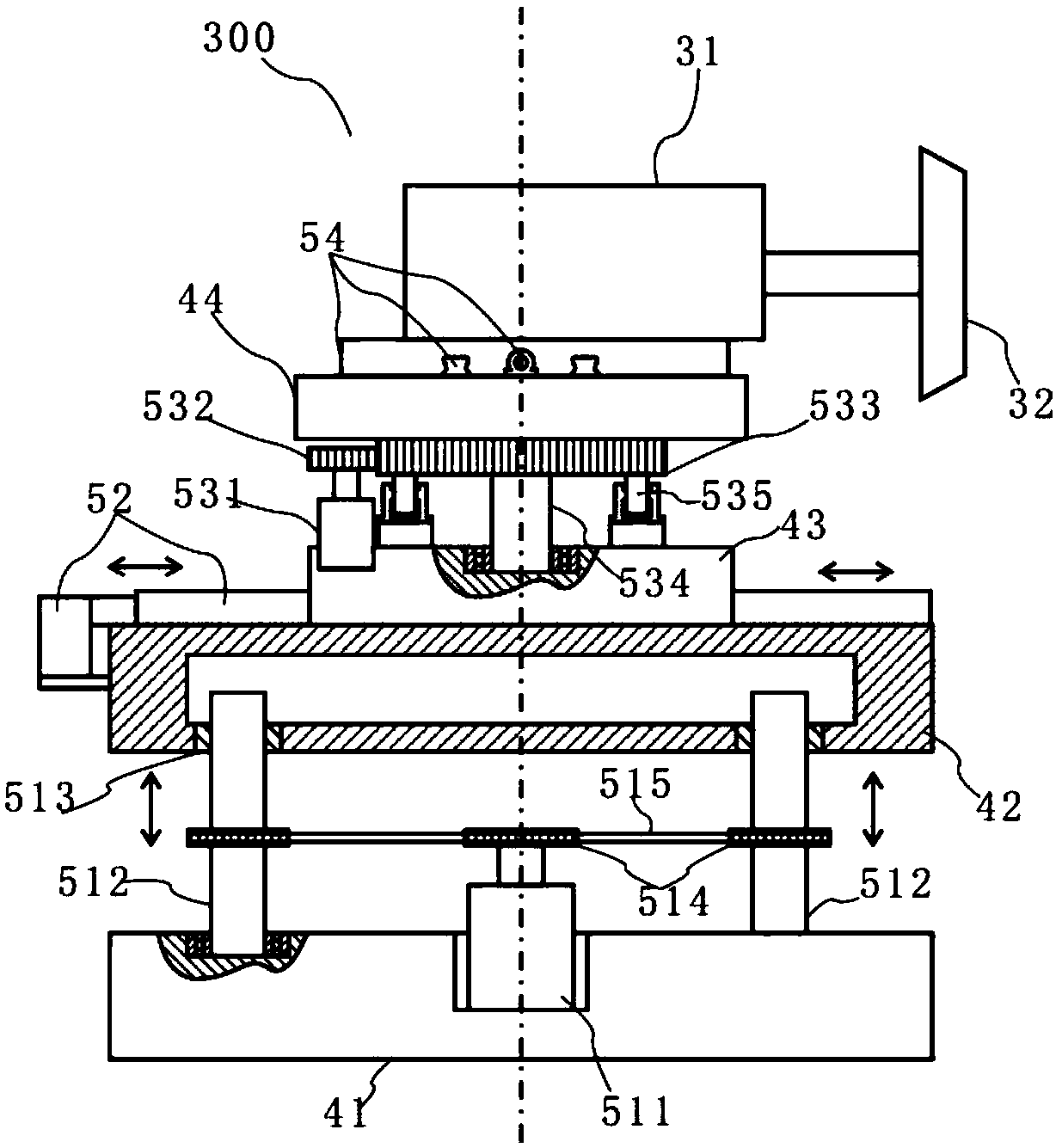
The invention relates to a grooving-chamfering machining process for an automobile brake pad, and a special grooving-chamfering combined machine. The grooving-chamfering machining process and the special grooving-chamfering combined machine are capable of meeting the machining requirements of straight grooves, inclined grooves, straight-sided chamfers, inclined-sided chamfers and the like, and high in automation level and machining consistency; and a workpiece is located in one process, and chamfering and grooving machining is completed in an assembly-line manner. Specifically, the grooving-chamfering combined machine comprises a workpiece slide table, a grooving unit and a chamfering unit, wherein each unit comprises a motor seat; each motor seat comprises a support base, a Z-axis base, aY-axis middle seat and a rotary upper seat; each Z-axis base is installed on the corresponding support base in a manner of lifting up and down through a Z-axis lifting mechanism; each Y-axis middle seat is installed on the corresponding Z-axis base in a manner of translating along Y axis through a Y-axis translation mechanism; each rotary upper seat is rotatably installed on the corresponding Y-axis middle seat around a central plane through a rotation mechanism; and a function motor is installed on each rotary upper seat in a manner of translating through a motor translation mechanism, and arotation center corresponds to an output shaft of the function motor when the function motor is located at the origin of a motor translation path.

Description

technical field [0001] The invention relates to the technical field of brake pad production equipment, in particular to a slotting and chamfering process for automobile brake pads and a special slotting and chamfering combination machine. Background technique [0002] In the braking system of a car, brake pads are the most critical safety parts. The brake pads play a decisive role in the quality of all braking effects. Brake pads are generally composed of steel plates, adhesive insulation layers and friction blocks. Steel plates must be coated It is installed to prevent rust, and the furnace temperature tracker is used to detect the temperature distribution during the coating process to ensure the quality. The friction block is composed of friction material and adhesive, which is squeezed on the brake disc or brake drum to generate friction during braking, so as to achieve the purpose of vehicle deceleration and braking. [0003] When the automobile brake lining is used, in...

Claims


Application Information

Patent Timeline
Patent Type & Authority Applications(China)
IPC IPC(8): B23P15/00B23P23/02
CPCB23P15/00B23P23/02B23P2700/50
Inventor 王华南
Owner 晋江市凯燕新材料研究院股份有限公司
Learn More