
Heat dissipation structure of detection module and detection equipment

A technology for detecting components and heat dissipation structures, applied in radiation detection devices, electrical equipment structural parts, electrical components, etc., can solve problems such as poor heat dissipation effect, temperature gradient, etc., and achieve the effect of avoiding temperature gradient problems

Active Publication Date: 2019-01-04
SHANGHAI UNITED IMAGING HEALTHCARE
View PDF10 Cites 4 Cited by
  • Summary
  • Abstract
  • Description
  • Claims
  • Application Information

AI Technical Summary

Problems solved by technology

[0004] Based on this, it is necessary to provide a heat dissipation structure and detection equipment for detection components to solve problems such as poor heat dissipation and easy temperature gradients.

Method used


Image

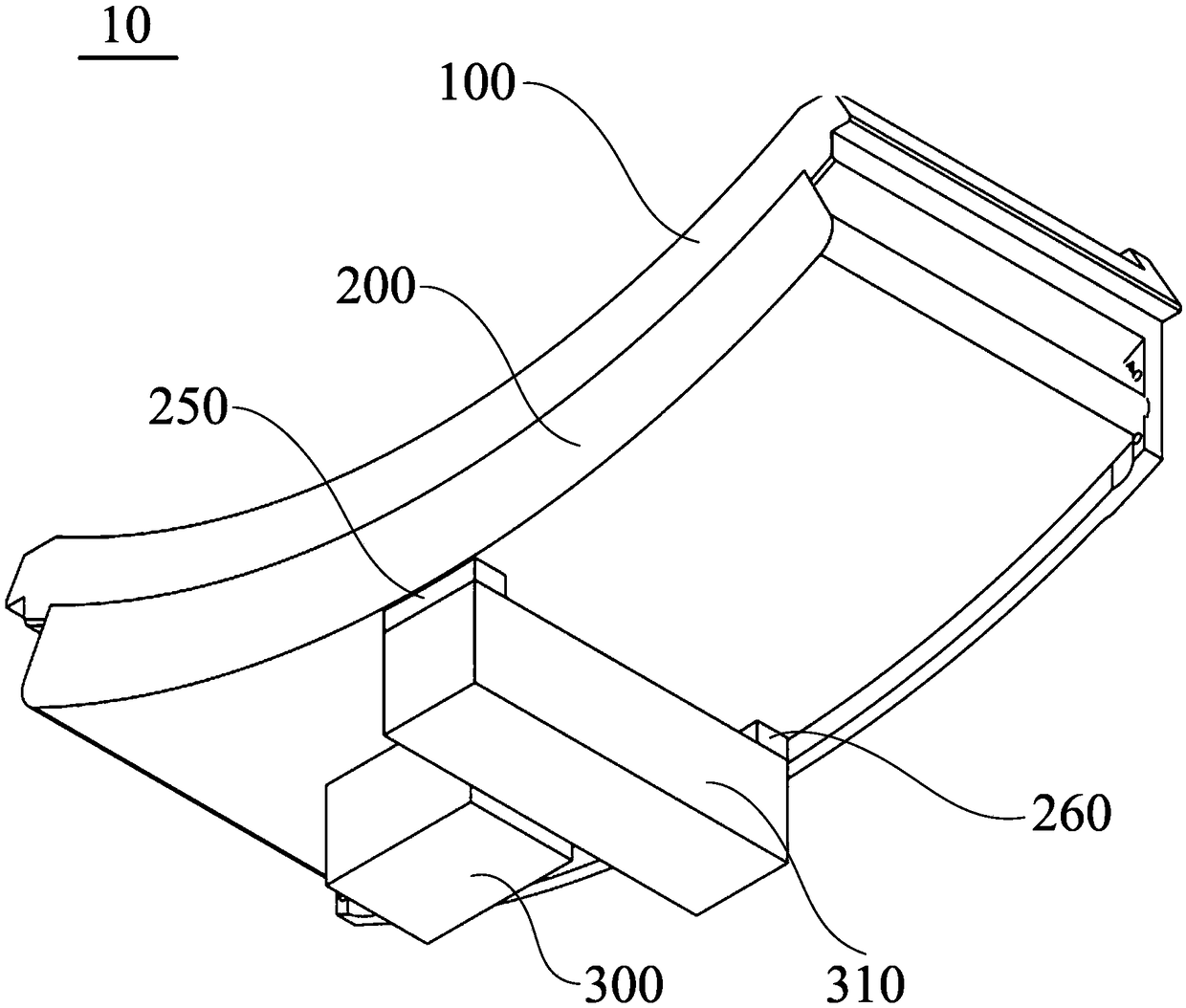
  • Heat dissipation structure of detection module and detection equipment
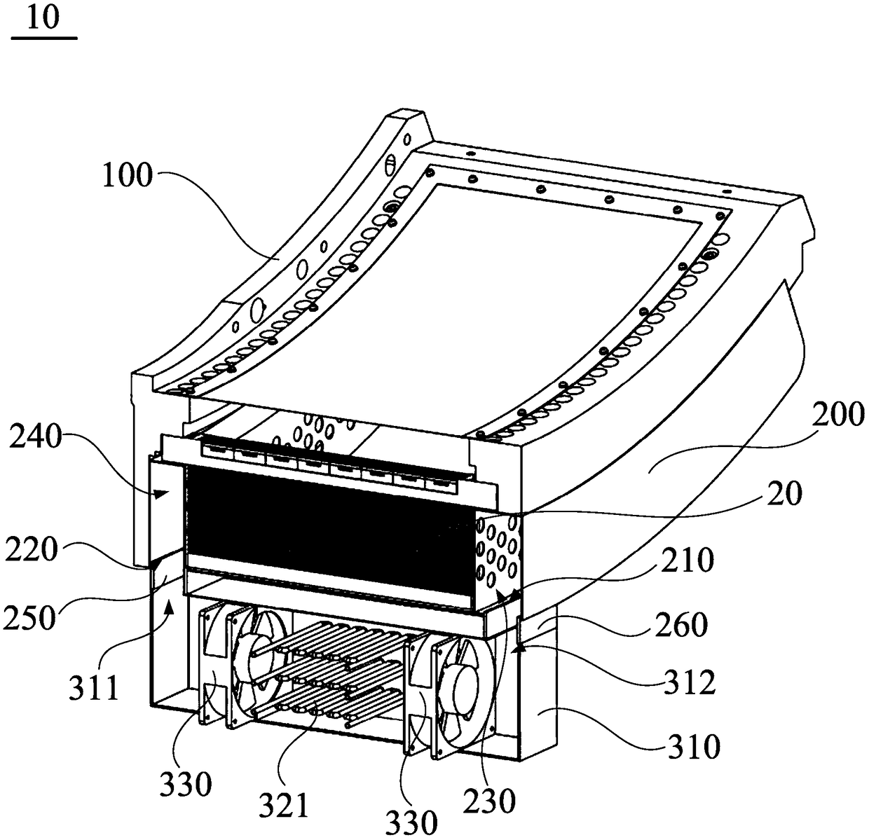
  • Heat dissipation structure of detection module and detection equipment
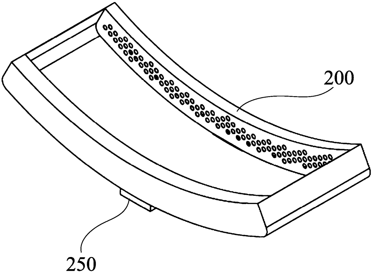
  • Heat dissipation structure of detection module and detection equipment

Examples


Embodiment Construction

[0040] In order to make the purpose, technical solution and advantages of the present invention clearer, the heat dissipation structure of the detection assembly and the detection equipment of the present invention will be further described in detail through the embodiments and in conjunction with the accompanying drawings. It should be understood that the specific embodiments described here are only used to explain the present invention, not to limit the present invention.

[0041] It should be noted that when an element is referred to as being “fixed” to another element, it can be directly on the other element or there can also be an intervening element. When an element is referred to as being "connected to" another element, it can be directly connected to the other element or intervening elements may also be present. In contrast, when an element is referred to as being "directly on" another element, there are no intervening elements present. The terms "vertical," "horizont...


PUM


Abstract

The invention relates to the technical field of medical equipment, in particular to a heat dissipation structure of a detection assembly, comprising a support body for mounting the detection assembly;A housing arranged on the support body, the housing and the support body forming a closed cavity for accommodating the detection assembly, and the housing is provided with an air flow inlet and an air flow outlet for guiding the air flow to dissipate heat to the detection assembly; And a cooling assembly including a housing, wherein the housing is provided with an air inlet and an air outlet, theair inlet is communicated with an air outlet, the air outlet is communicated with an air inlet, and the cooling assembly is used for cooling the air flow circulating between the housing and the housing. Since the circulation path of the entire airflow is completely closed, the airflow is not exchanged with the outside atmosphere, and the airflow circulating between the housing and the housing iscooled by the cooling assembly, so that the circulating airflow can be at a lower temperature level. Therefore, the heat dissipation structure of the invention can effectively cool the detection component and avoid the temperature gradient problem.

Description

technical field [0001] The invention relates to the technical field of medical equipment, in particular to a heat dissipation structure of a detection component and detection equipment. Background technique [0002] In the medical field, detection instruments such as CT machines or PET machines can detect the inside of the human body to check various indicators of the human body. Taking a CT machine as an example, it includes an X-ray tube and a detection assembly, and the detection assembly includes a detector for receiving X-ray signals and an electronic device for processing information read by X-rays. Since electronic devices generate a large amount of heat when they are in operation, heat dissipation must be performed on the electronic devices. [0003] At present, air cooling is mainly used for heat dissipation of electronic devices. Specifically, a fan is installed on the detection assembly, and the wind blows from one side of the detection assembly to the other side...

Claims


Application Information

Patent Timeline
Patent Type & Authority Applications(China)
IPC IPC(8): H05K7/20A61B6/03
CPCA61B6/03A61B6/42H05K7/20136
Inventor 叶婷
Owner SHANGHAI UNITED IMAGING HEALTHCARE
Learn More