
Regenerative energy recovery system based on flywheel energy storage and inverter feedback and control method

A flywheel energy storage and regenerative energy technology, which is applied in the direction of AC network load balancing, single-network parallel feeding arrangement, etc., can solve the problem of achieving optimality, insufficient utilization of regenerative electric energy, and affecting the relay protection and power quality of the power supply system and other issues, to achieve the effect of reducing complexity, overall economical and energy-saving effects, and scalability

Inactive Publication Date: 2019-01-04
沈阳微控新能源技术有限公司
View PDF5 Cites 12 Cited by
  • Summary
  • Abstract
  • Description
  • Claims
  • Application Information

AI Technical Summary

Problems solved by technology

This type of device partially utilizes the regenerative braking energy of the train, which has a certain energy-saving effect, but is limited by the load capacity of the low-voltage side or the load capacity of the medium-voltage side, the regenerative electric energy cannot be fully utilized, and it is possible to send power backward to the grid, affecting Relay Protection and Power Quality of Power Supply System
[0008] In order to solve the problem of recovery and utilization of regenerative braking energy in rail transit, it is difficult to achieve the best technical performance and economic indicators at the same time only by a single product

Method used


Image

  • Regenerative energy recovery system based on flywheel energy storage and inverter feedback and control method
  • Regenerative energy recovery system based on flywheel energy storage and inverter feedback and control method
  • Regenerative energy recovery system based on flywheel energy storage and inverter feedback and control method

Examples


Embodiment Construction

[0037] In order to make the object, technical solution and advantages of the present invention clearer, the present invention will be further described in detail below in conjunction with the accompanying drawings and specific embodiments. It should be understood that the specific embodiments described here are only used to explain the present invention, not to limit the present invention.

[0038] In order to make the description of the present disclosure more detailed and complete, the following provides an illustrative description of the implementation modes and specific examples of the present invention; but this is not the only form for implementing or using the specific examples of the present invention. The description covers features of various embodiments as well as method steps and their sequences for constructing and operating those embodiments. However, other embodiments can also be used to achieve the same or equivalent functions and step sequences.

[0039] The ...


PUM


Abstract

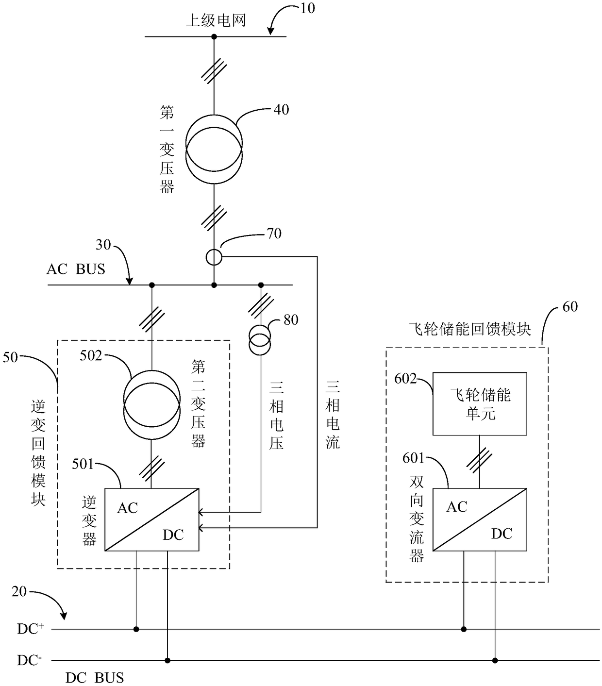
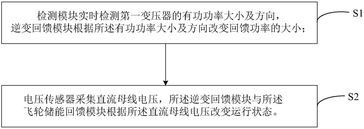
The invention relates to the technical field of urban rail transit regenerative energy recovery, in particular to a regenerative energy recovery system based on flywheel energy storage and inverter feedback, the system comprises at least one inverter feedback module, at least one flywheel energy storage feedback module, a detection module and a voltage sensor. The inverter feedback module and theflywheel energy storage feedback module in the system work in coordination with each other, and the regenerative energy is mainly fed back by the inverter, the regenerative energy is fully utilized, and the problem of the electric energy reverse transmission is solved; In addition, the flywheel energy storage feedback module does not need to be configured according to the maximum absorbed power demand, and the overall economy and energy saving effect of the system are better than the single inverter feedback and flywheel energy storage feedback. The control method of the system provided by theinvention decouples the inverter feedback module and the flywheel energy storage feedback module in control, does not need to rely on mutual communication, reduces the complexity of system control, has expansibility, and is convenient for construction and operation and maintenance.

Description

technical field [0001] The invention relates to the technical field of urban rail transit regenerative energy recovery, in particular to a regenerative energy recovery system and control method based on flywheel energy storage and inverter feedback. Background technique [0002] Electricity accounts for about 30-40% of the operating costs of rail transit such as subways. At present, rail trains generally adopt variable voltage and variable frequency (VVVF) transmission mode. When the train brakes, the electric energy can be fed back to the traction grid for use by other trains. This part of the regenerative braking energy is very considerable. In some traction grids, regenerative braking The energy accounts for about 30% of the total electric energy of train traction, and has great energy-saving space. [0003] Commonly used regenerative braking energy absorption methods mainly include the following technologies: resistive energy consumption type, supercapacitor energy stor...

Claims


Application Information

Patent Timeline
Patent Type & Authority Applications(China)
IPC IPC(8): H02J3/38H02J3/30
CPCH02J3/30H02J3/38Y02E60/16
Inventor 江卫良张庆源陈烨郑琦葛自强
Owner 沈阳微控新能源技术有限公司
Learn More