
Sludge drying and gasification coupled coal-fired power generation system and process method thereof

A power generation system and sludge drying technology, applied in gasification process, combustion method, chemical industry, etc., can solve the problems of high energy consumption for drying, difficulty in reducing the level of sludge combustion, and increased cost of sludge incineration, etc., to achieve Reduce system investment and operating costs, facilitate large-scale amplification, and improve energy utilization efficiency

Inactive Publication Date: 2019-01-01
SHANGHAI BOILER WORKS
View PDF8 Cites 15 Cited by
  • Summary
  • Abstract
  • Description
  • Claims
  • Application Information

AI Technical Summary

Problems solved by technology

However, there are also many problems in sludge incineration treatment. It is very difficult to reduce the moisture content of sludge to a level that can be burned, and the drying energy consumption is high. If the sludge is not dried, coal needs to be added to the sludge, so that the sludge The cost of mud incineration has increased significantly

Method used


Image

  • Sludge drying and gasification coupled coal-fired power generation system and process method thereof
  • Sludge drying and gasification coupled coal-fired power generation system and process method thereof
  • Sludge drying and gasification coupled coal-fired power generation system and process method thereof

Examples


Embodiment Construction

[0034] The present invention will be further described below in conjunction with specific implementation examples.

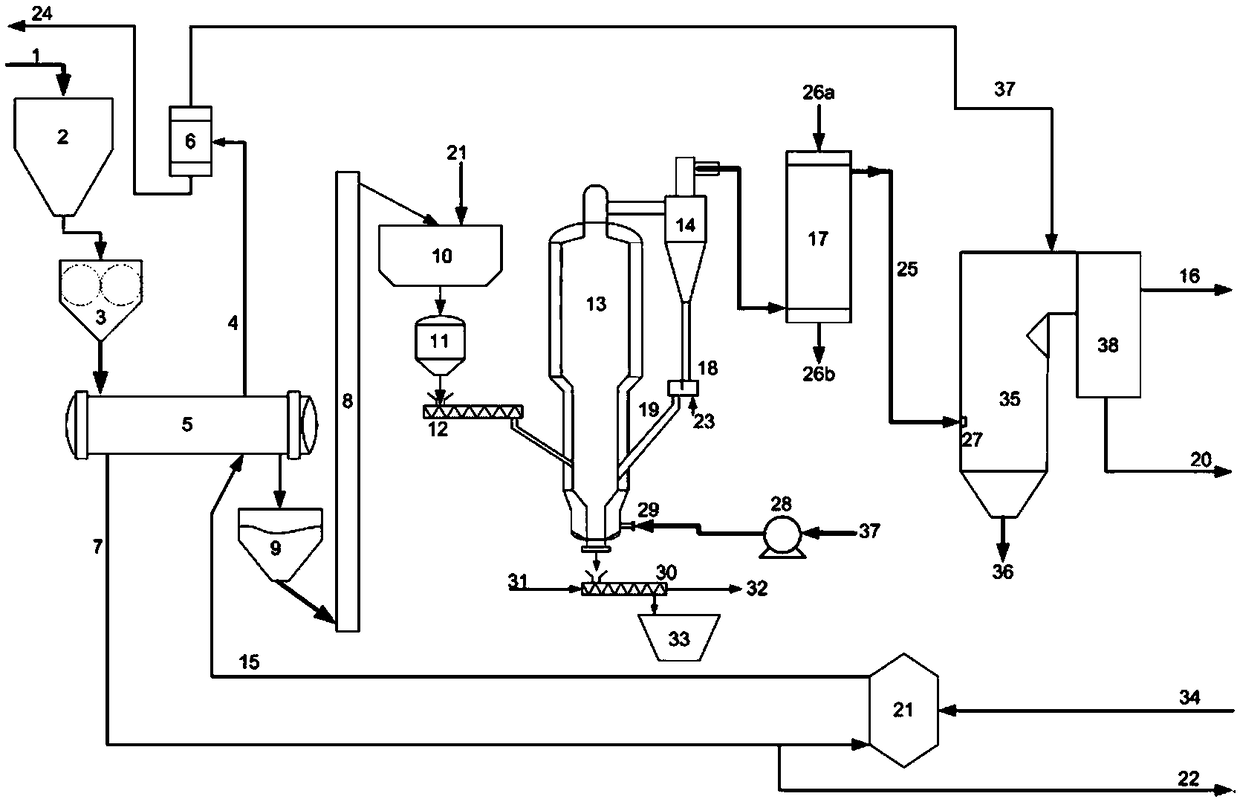
[0035] The invention provides a coal-fired power generation system coupled with sludge drying and gasification, which makes full use of the surplus low-grade steam of the coal-fired boiler power generation system, uses this part of the heat source to dry the sludge, and then performs gasification. The fuel gas produced is sent to the boiler system for combustion.

[0036] figure 1Schematic diagram of the structure of the sludge drying gasification coupled coal-fired power generation system provided for this example. The sludge drying gasification coupled coal-fired power generation system is mainly composed of a sludge indirect drying unit and a sludge gasification combustion unit It is composed of workshop equipment such as gas incineration unit.

[0037] The wet sludge raw material 1 enters the sludge raw material bin 2, and the indirect sludge drying unit m...


PUM


Abstract

The invention provides a sludge drying and gasification coupled coal-fired power generation system. The sludge drying and gasification coupled coal-fired power generation system is characterized by comprising a sludge indirect drying unit, a sludge gasification and combustion unit and a gas incineration unit, wherein the sludge indirect drying unit is used for performing indirect drying and dewatering on sludge raw materials stored in a sludge storage warehouse by steam; waste gas produced by the sludge storage warehouse and exhaust gas produced by indirect drying and dewatering of the sludgeraw materials is exhaust gas; the sludge gasification and combustion unit is used for conveying and gasifying the sludge being subjected to indirect drying and dewatering to produce flammable gas; thegas incineration unit is used for conveying the flammable gas produced by the sludge gasification and combustion unit and the exhaust gas to a coal-fired boiler for combustion. Another technical scheme of the invention is to provide a sludge drying and gasification coupled coal-fired power generation method. By adopting the system and the method provided by the invention, sludge combustion and power generation are realized by feeding the combustible gas obtained by sludge drying and gasification together with raw coal into the coal-fired boiler for combustion and replacing part of coal-firedload without affecting a coal-fired boiler system. The system provided by the invention runs stably and reliably, is easy to be enlarged, and is environmentally friendly and energy-saving.

Description

technical field [0001] The invention relates to a coal-fired power generation system coupled with sludge drying and gasification and a process method thereof, belonging to the technical field of solid waste treatment. Background technique [0002] Promoting the construction of ecological civilization has been deeply rooted in the hearts of the people, and the problem of urban water pollution has also attracted increasing attention from all walks of life. In recent years, with the acceleration of my country's urban sewage treatment efforts and the construction of sewage treatment facilities, the urban sewage treatment rate has continued to increase. As of the end of December 2017, a total of 5,027 sewage treatment plants have been built in cities and counties (hereinafter referred to as towns, excluding other administrative towns) across the country, with a sewage treatment capacity of 188 million cubic meters per day, and annual sewage with a water content of 80%. More than...

Claims


Application Information

Patent Timeline
Patent Type & Authority Applications(China)
IPC IPC(8): C02F11/12C10J3/20C10J3/84F23G5/027F23G5/04F23G5/16F23G5/46F23G7/00F23G7/06
CPCC02F11/12C10J3/20C10J3/84C10J2300/0909C10J2300/0946C10J2300/1671F23G5/027F23G5/04F23G5/16F23G5/46F23G7/001F23G7/06F23G2201/10F23G2201/40F23G2202/103F23G2206/10F23G2206/20F23G2209/12F23G2209/14Y02P20/10
Inventor 倪建军池国镇陈子珍张翔
Owner SHANGHAI BOILER WORKS
Learn More