
A desktop four-axis linkage fiber winding machine for grid structure forming

A fiber winding machine and four-axis linkage technology, which is applied in the field of composite material forming, can solve the problem that the winding machine cannot meet the requirements of mesh structure winding micro-spacecraft components, etc., to reduce fiber accumulation and overhead defects, easy maintenance and use, The effect of improving performance

Active Publication Date: 2020-09-01
HARBIN INST OF TECH
View PDF3 Cites 0 Cited by
  • Summary
  • Abstract
  • Description
  • Claims
  • Application Information

AI Technical Summary

Problems solved by technology

[0003] In order to solve the problem that the existing winding machine cannot satisfy the winding of grid structure and the winding and forming of micro-spacecraft components, the present invention further provides a desktop four-axis linkage fiber winding machine for grid structure forming

Method used


Image

  • A desktop four-axis linkage fiber winding machine for grid structure forming
  • A desktop four-axis linkage fiber winding machine for grid structure forming
  • A desktop four-axis linkage fiber winding machine for grid structure forming

Examples


specific Embodiment approach 1

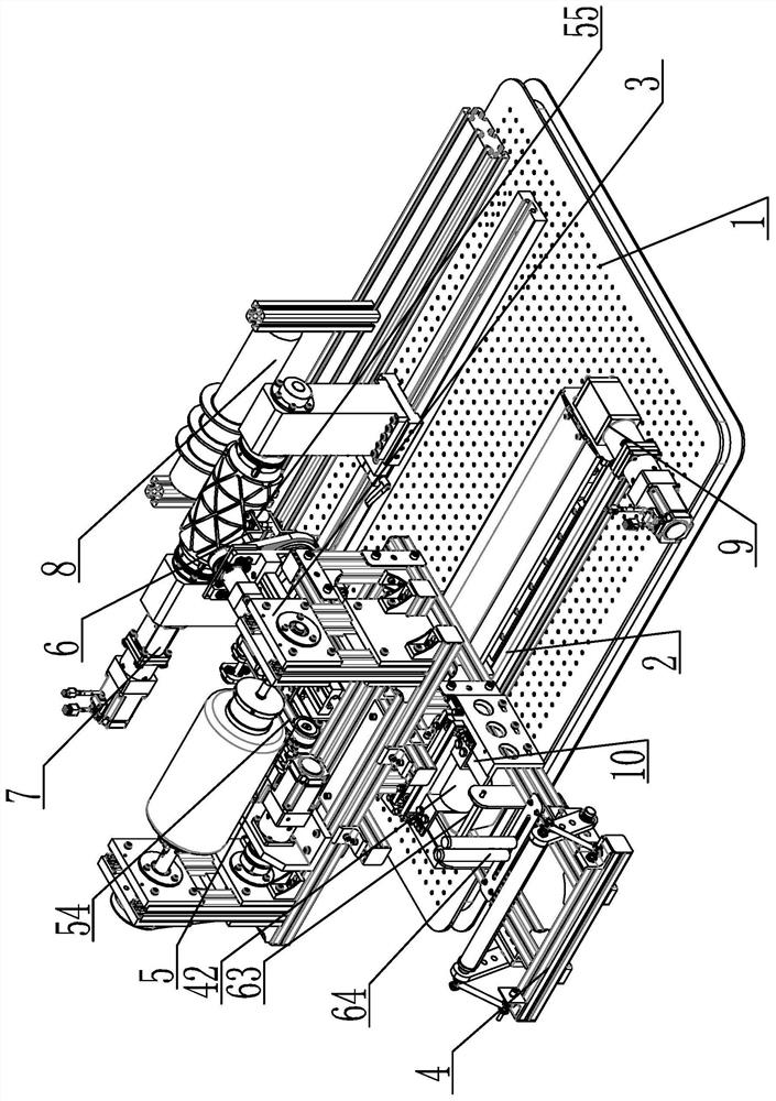
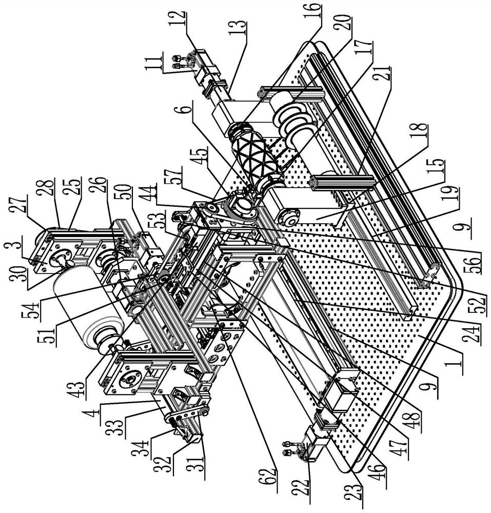
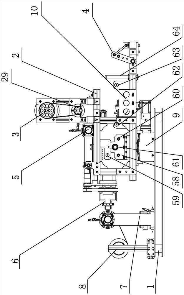
[0016] Specific implementation mode one: combine Figure 1-Figure 8 Describe this embodiment, a desktop four-axis linkage fiber winding machine for grid structure forming described in this embodiment, which includes a machine tool platform 1, a moving frame body 2, a frame body moving drive mechanism 9, and a fiber unwinding mechanism 3. Yarn picking mechanism 4, rubber dipping mechanism 10, telescopic arm assembly 5, thread nozzle assembly 6, main shaft rotating part 7 and circumferential rib winding assembly 8; frame moving drive mechanism 9, main shaft rotating part 7 and circumferential rib winding The component 8 is installed on the machine tool platform 1, the main shaft rotating part 7 is located between the frame body moving drive mechanism 9 and the circumferential rib winding assembly 8, the moving frame body 2 is installed on the frame body moving drive mechanism 9, the fiber unwinding mechanism 3, The yarn picking mechanism 4 , the dipping mechanism 10 , the telesc...

specific Embodiment approach 2

[0018] Specific implementation mode two: combination Figure 1-Figure 5 Describe this embodiment, a desktop four-axis linkage fiber winding machine for grid structure forming described in this embodiment, the main shaft rotating part 7 includes a main shaft servo motor 11, a reducer 12, a main shaft servo motor coupling 13, Main shaft 14, mandrel, main shaft chuck 16, support chuck 17, slider 18, slide rail 19 and two main shaft supporting columns 15, main shaft servo motor 11, reducer 12, main shaft servo motor coupling 13, main shaft 14 , mandrel, main shaft chuck 16, and support chuck 17 are fixedly connected along a straight line in turn, and the outer casing of the main shaft servo motor 11 is fixedly connected with the housing of the reducer 12 and the bracket end of the main shaft servo motor coupling 13, and the main shaft servo motor The other end of the shaft coupling 13 is fixedly connected with a main shaft support column 15, the main shaft 14 is rotatably connecte...

specific Embodiment approach 3

[0019] Specific implementation mode three: combination Figure 1-Figure 5 Describe this embodiment, a desktop four-axis linkage fiber winding machine for grid structure forming described in this embodiment, the circumferential rib winding assembly 8 includes a creel 21 and a yarn cluster 20, and the yarn cluster 20 is installed on the creel 21, creel 21 is fixedly installed on machine tool platform 1. Other methods are the same as in the second embodiment.


PUM


Abstract

The invention provides a desktop type four-axis linkage fiber winding machine for molding a grid structure and relates to one fiber winding machine, aiming at solving the problems that an existing winding machine cannot meet winding of the grid structure and winding molding of a mini-type spacecraft component. The desktop type four-axis linkage fiber winding machine comprises a machine tool platform, a movable frame body, a frame body movement driving mechanism, a fiber rewinding mechanism, a yarn picking mechanism, a glue immersing mechanism, a retractable arm assembly, a silk nozzle assembly, a main shaft rotary part and an annular rib winding assembly; the frame body movement driving mechanism, the main shaft rotary part and the annular rib winding assembly are mounted on the machine tool platform; the main shaft rotary part is located between the frame body movement driving mechanism and the annular rib winding assembly; the movable frame body is mounted on the frame body movementdriving mechanism; the fiber rewinding mechanism, the yarn picking mechanism, the glue immersing mechanism, the retractable arm assembly and the silk nozzle assembly are mounted on the movable frame body. The desktop type four-axis linkage fiber winding machine belongs to the field of molding of composite materials.

Description

technical field [0001] The invention relates to a fiber winding machine, in particular to a desktop four-axis linkage fiber winding machine for forming a grid structure, which belongs to the field of composite material forming. Background technique [0002] Filament winding is an automatic molding method for manufacturing fiber-reinforced resin-based composite materials. It winds continuous fibers or cloth tapes and prepreg yarns impregnated with resin on the mandrel according to certain rules, and then solidifies and demoulds to obtain products. , the product has the characteristics of light weight, high strength, corrosion resistance, etc., and the fiber winding machine is the key equipment to realize this process. In the field of aerospace, CNC fiber winding machines are mainly used for composite material molding of rockets, missile engine casings, nozzles, and satellite structural parts. With the development of my country's aerospace industry and space applications, mic...

Claims


Application Information

Patent Timeline
Patent Type & Authority Patents(China)
IPC IPC(8): B29C70/32
CPCB29C70/32
Inventor 韩振宇张鹏金鸿宇富宏亚邵忠喜
Owner HARBIN INST OF TECH
Learn More