Monitoring method and system for remained charge of battery pack
A technology of remaining power and battery packs, applied in the direction of measuring electrical variables, measuring electricity, measuring devices, etc.
- Summary
- Abstract
- Description
- Claims
- Application Information
AI Technical Summary
Problems solved by technology
Method used
Image
Examples
Embodiment 1
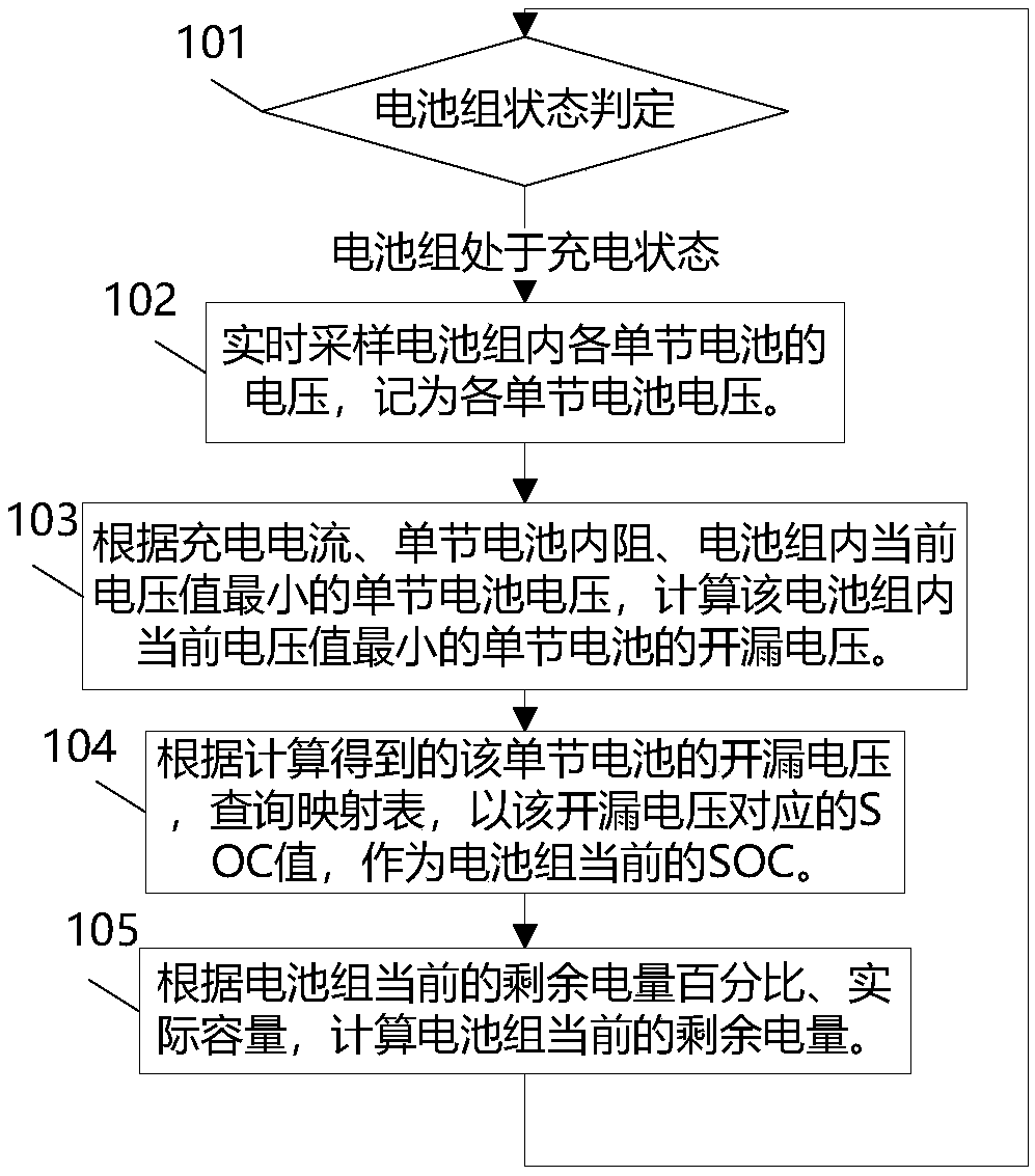
[0103] see figure 1 As shown, this embodiment provides a method for monitoring the remaining power of a battery pack, which mainly includes the following steps:
[0104] Step 101: Monitor the current state of the battery pack, and determine the state of the battery pack.
[0105] If the battery is currently in a charging state, execute steps 102-105.
[0106] The situation that the battery pack is currently in other states can be handled according to the prior art, but not limited to.
[0107] The battery pack in this embodiment generally consists of one or more single-cell batteries with the same design parameters.
[0108] The single battery described in this embodiment can be: a series unit composed of multiple single batteries connected in parallel. At this time, the voltage of a single battery is the voltage of the unit composed of multiple single batteries connected in parallel, and the current of a single battery is the current of the battery pack. Since the current ...
Embodiment 2
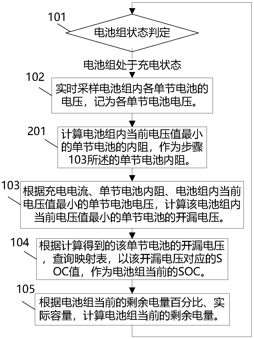
[0143] see figure 2 As shown, the difference between this embodiment and embodiment 1 is:
[0144] The internal resistance of a single battery in this embodiment is obtained through real-time monitoring during the charging process, and the scheme is as follows:
[0145] Also include between step 102 and step 103:
[0146] Step 201: Calculate the internal resistance of the single battery with the smallest current voltage value in the battery pack as the internal resistance of the single battery described in step 103.
[0147] In this embodiment, a switch circuit may be connected in series in the charging circuit. When the switch circuit is turned off, the charging circuit of the battery pack is disconnected; when the switch circuit is turned on, the charging circuit of the battery pack is turned on.
[0148] By measuring the moment before and after the switch circuit is turned on, the voltage and current of the single battery with the smallest current voltage value in the ba...
Embodiment 3
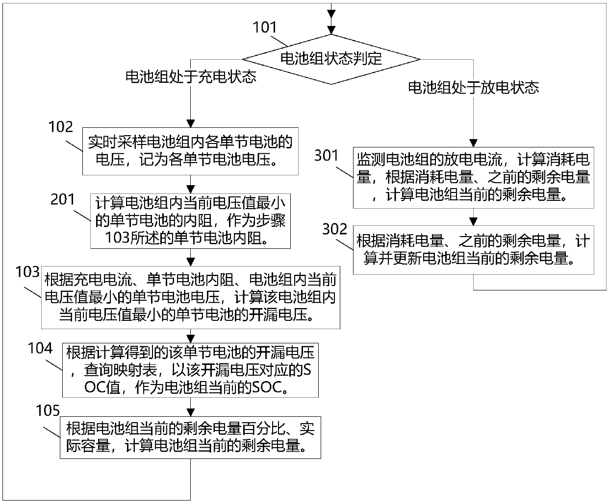
[0161] see image 3 As shown, the differences between this embodiment and embodiment 2 are:
[0162] After step 101, when it is determined that the battery pack is currently in a discharging state, steps 301-302 are executed according to this embodiment. details as follows:
[0163] Step 301: Monitor the discharge current of the battery pack, calculate the power consumption, and calculate the current remaining power of the battery pack according to the power consumption and the previous remaining power.
[0164] In this embodiment, the discharge current of the battery pack is regularly monitored, and the current power consumption is calculated according to the discharge current.
[0165] Record the calculation start time of the current calculated power consumption as T1;
[0166] Record the calculation cut-off time of the current calculated power consumption as T2;
[0167] Record the power consumption as Q, according to the following function
[0168] Calculate the pow...
PUM
 Abstract
Description
Claims
Application Information
 - Generate Ideas
- Intellectual Property
- Life Sciences
- Materials
- Tech Scout
- Unparalleled Data Quality
- Higher Quality Content
- 60% Fewer Hallucinations
Browse by: Latest US Patents, China's latest patents, Technical Efficacy Thesaurus, Application Domain, Technology Topic, Popular Technical Reports.
© 2025 PatSnap. All rights reserved.Legal|Privacy policy|Modern Slavery Act Transparency Statement|Sitemap|About US| Contact US: help@patsnap.com


