Tunnel bottom structure of high water head water enriched tunnel and water draining method

A water-rich tunnel and high water head technology, applied in drainage, earthwork drilling, safety devices, etc., can solve problems such as the inability to ensure the effective operation of the drainage system, potential safety hazards in long-term stability, uplift and cracking of the inverted arch structure, etc., to achieve Simple construction, little impact on the construction period, and low cost

Pending Publication Date: 2018-12-25
中铁西南科学研究院有限公司
View PDF7 Cites 2 Cited by
  • Summary
  • Abstract
  • Description
  • Claims
  • Application Information

AI Technical Summary

Problems solved by technology

[0002] At present, in high-head water-rich tunnels, drainage systems are usually installed on the side walls and arches of the tunnel, that is, blind ditch, filter layer, and waterproof board are installed between the primary support and the secondary lining of the side wall and vault. Drainage holes are set at the bottom of the second lining side wall (generally, the longitudinal distance is 5-10m); the surrounding rock seepage water is directly discharged into the drainage ditch at the bottom of the tunnel through the blind ditch and the reverse filter layer, and no drainage system is usually set at the bottom of the tunnel. The inverted arch is directly in contact with the surrounding rock; with the current level of construction technology, the drainage system at the bottom of the tunnel is mainly based on blind ditch, filter layer, and waterproof board, which cannot guarantee the effective operation of the drainage system; because the permeable cushion during construction and blind pipes are easily compacted or blocked when pouring concrete, resulting in the failure of the drainage system; therefore, the drainage system is often not installed at the bottom of the tunnel during design or construction, and the tunnel bottom structure of the tunnel bottom drainage system is usually set , its long-term stability also has safety hazards; in this case, when the drainage system is working normally, the water pressure acting on the tunnel superstructure is very small; usually it can be ignored, but for the high water head and rich water section, the effect The water pressure on the inverted arch of the tunnel cannot be ignored; there is no drainage under the tunnel, and due to the barrier of the concrete material of the inverted arch, the water in the surrounding rock below the tunnel bottom cannot be smoothly discharged from the drain hole at the bottom of the side wall; The arch bears a large water pressure load. When the value of the water pressure load reaches a certain value, the inverted arch structure is prone to uplift and cracking; The establishment of the drainage system leads to the cracking of the tunnel bottom structure and the lifting of the ballast bed caused by the high water pressure on it, and there is an increasing trend of such cases; the cracking of the tunnel bottom structure and the lifting of the ballast bed seriously affect the tunnel. The quality of the project, if it is light, will only damage the structure, and if it is serious, it will affect the passage of similar vehicles, or even cause outage. It will be even more harmful to high-speed railway tunnels that use ballastless ballast beds.

Method used


Image

  • Tunnel bottom structure of high water head water enriched tunnel and water draining method
  • Tunnel bottom structure of high water head water enriched tunnel and water draining method
  • Tunnel bottom structure of high water head water enriched tunnel and water draining method

Examples


Embodiment Construction

[0027] The present invention will be further described below in conjunction with the accompanying drawings and specific embodiments.

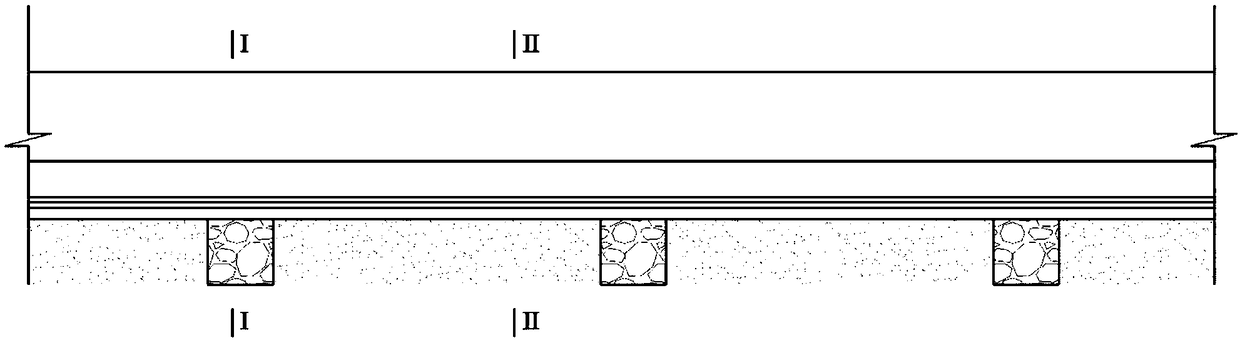
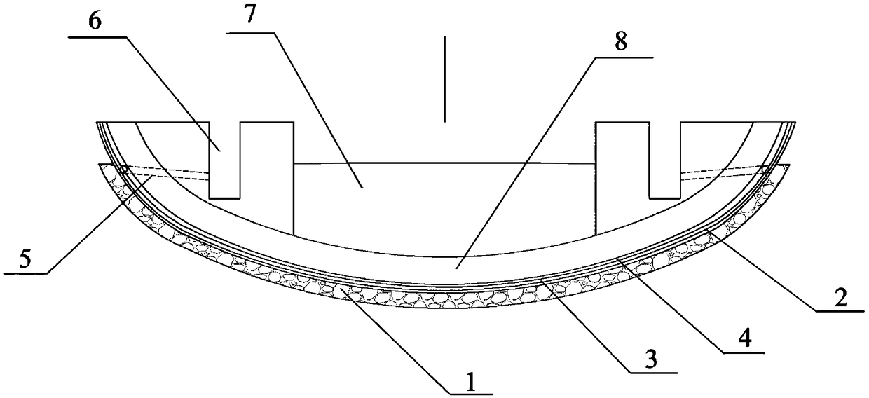
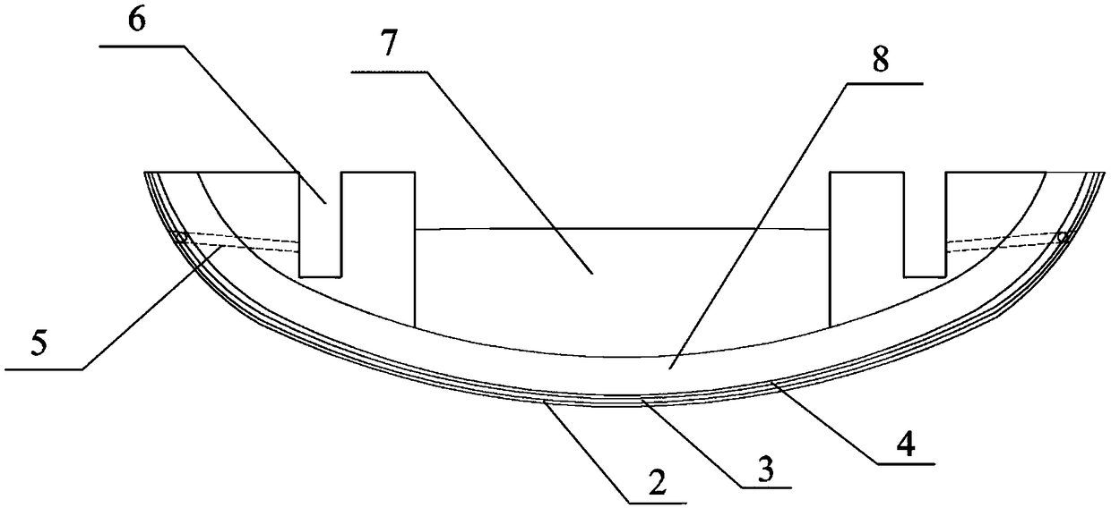
[0028] A tunnel bottom structure of a high-head water-rich tunnel, comprising a drainage groove 1 arranged along the tunnel ring in the surrounding rock of the tunnel bottom, the drainage groove 1 is connected to the drainage ditch 6; the drainage groove 1 is filled with permeable materials; the inverted arch surface of the tunnel bottom The inner side of the drainage tank 1 is the primary support 2 made of concrete; the non-woven fabric 3 and the waterproof layer 4 are sequentially arranged from the surface of the primary support 2 to the inverted arch 8 .

[0029] The drainage groove 1 extends to the foot of the wall, and communicates with the drainage ditch 6 through the drain hole 5 arranged at the foot of the wall of the drainage groove 1 .

[0030] The cross-section of the drainage groove 1 is a square structure; multiple drainage grooves...


PUM


Abstract

The invention discloses a tunnel bottom structure of a high water head water enriched tunnel and a water draining method. The tunnel structure comprises water draining grooves annularly formed in tunnel bottom surrounding rock along the tunnel, and the water draining grooves are connected with water draining ditches; the water draining grooves are filled with seepy materials; the inner side of thewater draining groove in the surface of an inverted arch of the tunnel bottom is an initial branch composed of concrete; a non-woven fabric and a water-proof layer are successively arranged from thesurface of the initial branch to the inverted arch; the tunnel bottom structure can effectively reduce water pressure acted on the inverted arch to avoid fracturing of the tunnel bottom structure dueto the water pressure of the inverted arch, uplifting of a ballast bed and the frost boiling and mud coming phenomenon caused by the above problems.

Description

technical field [0001] The invention relates to a tunnel drainage construction method, in particular to a tunnel bottom structure and a drainage method of a high-head water-rich tunnel. Background technique [0002] At present, in high-head water-rich tunnels, drainage systems are usually installed on the side walls and arches of the tunnel, that is, blind ditch, filter layer, and waterproof board are installed between the primary support and the secondary lining of the side wall and vault. Drainage holes are set at the bottom of the second lining side wall (generally, the longitudinal distance is 5-10m); the surrounding rock seepage water is directly discharged into the drainage ditch at the bottom of the tunnel through the blind ditch and the reverse filter layer, and no drainage system is usually set at the bottom of the tunnel. The inverted arch is directly in contact with the surrounding rock; with the current level of construction technology, the drainage system at the...

Claims


Application Information

Patent Timeline
Patent Type & Authority Applications(China)
IPC IPC(8): E21F16/02
CPCE21F16/02
Inventor 郑波王建宇吴剑高红兵陈礼伟王刚杜俊郭瑞
Owner 中铁西南科学研究院有限公司
Why Eureka
Try Eureka