
combing machine

A combing machine and combing technology, applied in the direction of combing machine, textile and paper making, fiber processing, etc.

Active Publication Date: 2021-10-22
TRUETZSCHLER GRP SE
View PDF5 Cites 0 Cited by
  • Summary
  • Abstract
  • Description
  • Claims
  • Application Information

AI Technical Summary

Problems solved by technology

However, it is disadvantageous for many maintenance flaps to require a corresponding number of sensors and there is a high wiring outlay for electrically connecting each sensor to the controller

Method used


Image

  • combing machine
  • combing machine
  • combing machine

Examples


Embodiment Construction

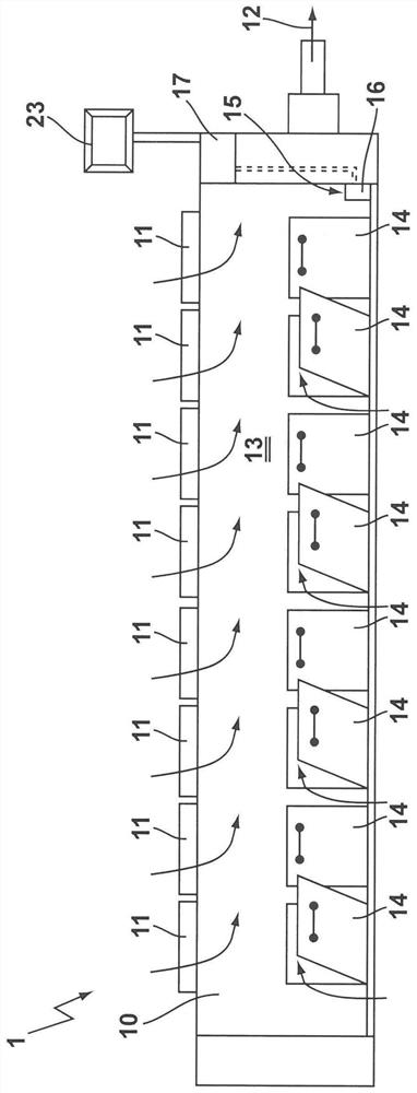
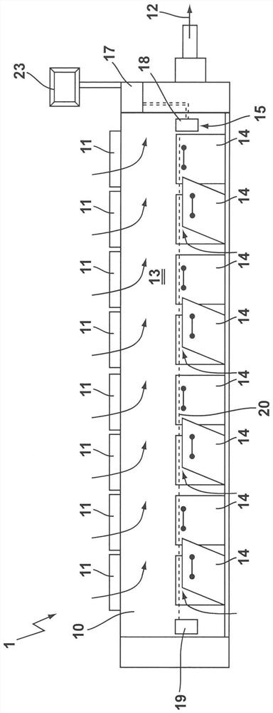
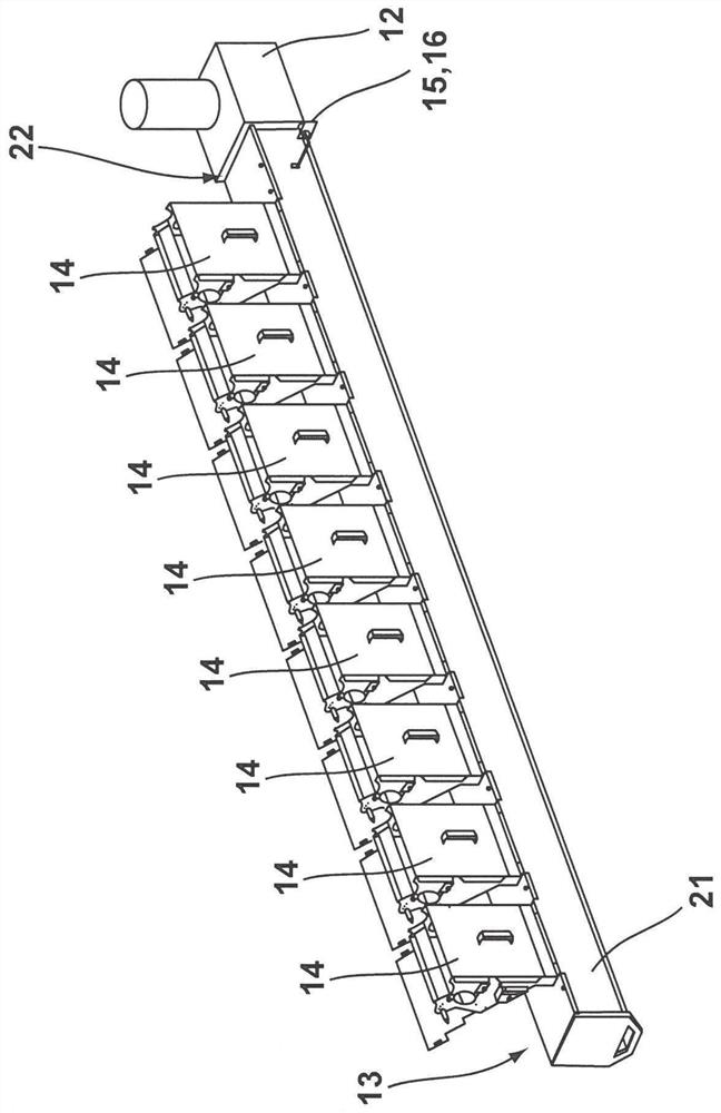
[0020] figure 1 with figure 2 A combing machine 1 with a housing 10 is shown schematically in each case. A plurality of combing units 11 are accommodated in the housing 10 , which are designed to process the laps, not shown in detail, which are fed to the combing units 11 . For example, eight maintenance flaps 14 are arranged on the front side of the housing 10 , wherein the closed state of the maintenance flap and the open state of the maintenance flap are respectively shown.

[0021] The combing machine also has a controller 17 which is connected to the combing unit 11 and controls the combing unit 11 via the controller. The suction mechanism 12 is shown schematically and the components carded from the lap are sucked by the air flow. Simplified here, the suction mechanism 12 is only connected to the housing 10, wherein a collection chamber 13 is formed in the interior of the housing 10 in a manner not shown in detail, in which the combed components from the combing unit ...


PUM


Abstract

The subject of the invention is a combing machine (1) with a plurality of combing units (11) housed inside a common housing (10), which are configured for processing The fiber strip of (11), wherein is provided with suction mechanism (12), utilizes suction mechanism to draw out from at least one collection chamber (13) the composition combed out from combing unit (11), and for each combing The unit (11) is attached with a maintenance hole with a maintenance flap (14), through which the collection chamber (13) is accessible from the outside. According to the invention, a sensor element (15) is provided, by means of which the closed state of at least two maintenance flaps (14) can be monitored.

Description

technical field [0001] The invention relates to a combing machine with a plurality of combing units accommodated in a common housing, the combing units being configured for processing a fiber sliver guided to the combing unit, wherein a suction mechanism is provided, The components combed from the combing units are led out of at least one collection chamber by means of a suction mechanism, and wherein a maintenance opening with a maintenance flap is attached to each combing unit, through which the collection chamber can be accessed from the outside . Background technique [0002] Combing machines usually have combing heads arranged side by side, for example in a row of 8, which are each arranged in front of the sliver reel. The fiber web combed and discharged by the individual combing heads is combined by known means to form a fiber strand and is conveyed on a guide table transversely to the material flow direction of the combing unit to the downstream drafting unit. The f...

Claims


Application Information

Patent Timeline
Patent Type & Authority Patents(China)
IPC IPC(8): D01G19/28D01G19/00
CPCD01G19/00D01G19/28D01G19/22
Inventor 得克·美尔
Owner TRUETZSCHLER GRP SE
Learn More