Structure for lower portion of vehicle body

A body, front and rear technology of the body, applied to the superstructure, superstructure sub-assemblies, vehicle components, etc., can solve the problem of difficulty in ensuring the minimum ground clearance of the muffler

Active Publication Date: 2018-12-21
HONDA MOTOR CO LTD
View PDF8 Cites 4 Cited by
  • Summary
  • Abstract
  • Description
  • Claims
  • Application Information

AI Technical Summary

Problems solved by technology

Therefore, it is difficult to ensure the minimum ground clearance of the muffler
[0011] Furthermore, when the muffler is shifted in the front-rear direction of the cross member, even if the cross member is deformed, it is difficult to press the muffler downward by the cross member.

Method used


Image

  • Structure for lower portion of vehicle body
  • Structure for lower portion of vehicle body
  • Structure for lower portion of vehicle body

Examples


no. 1 approach

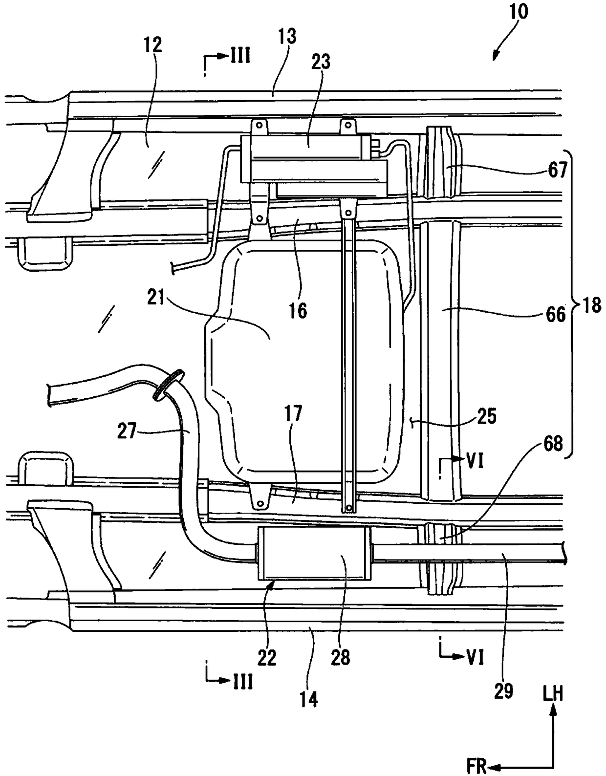
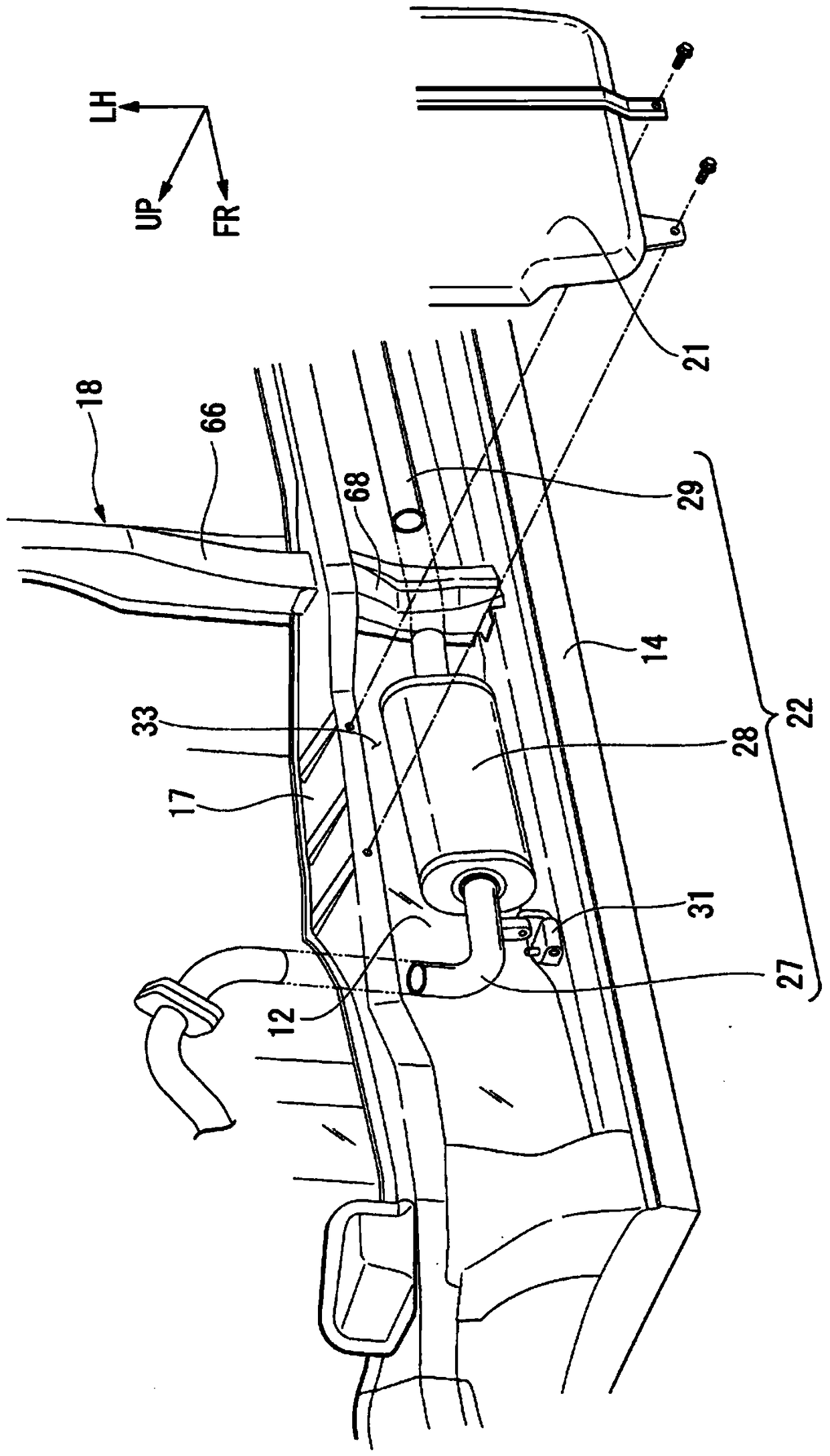
[0062] Such as figure 1 As shown, the vehicle body lower structure 10 includes a floor 12 , a left side sill 13 provided on the left side of the floor 12 , a right side sill 14 provided on the right side of the floor 12 , and a left floor frame 16 provided inside the left side sill 13 . , and the right floor frame 17 provided inside the right side sill 14 .

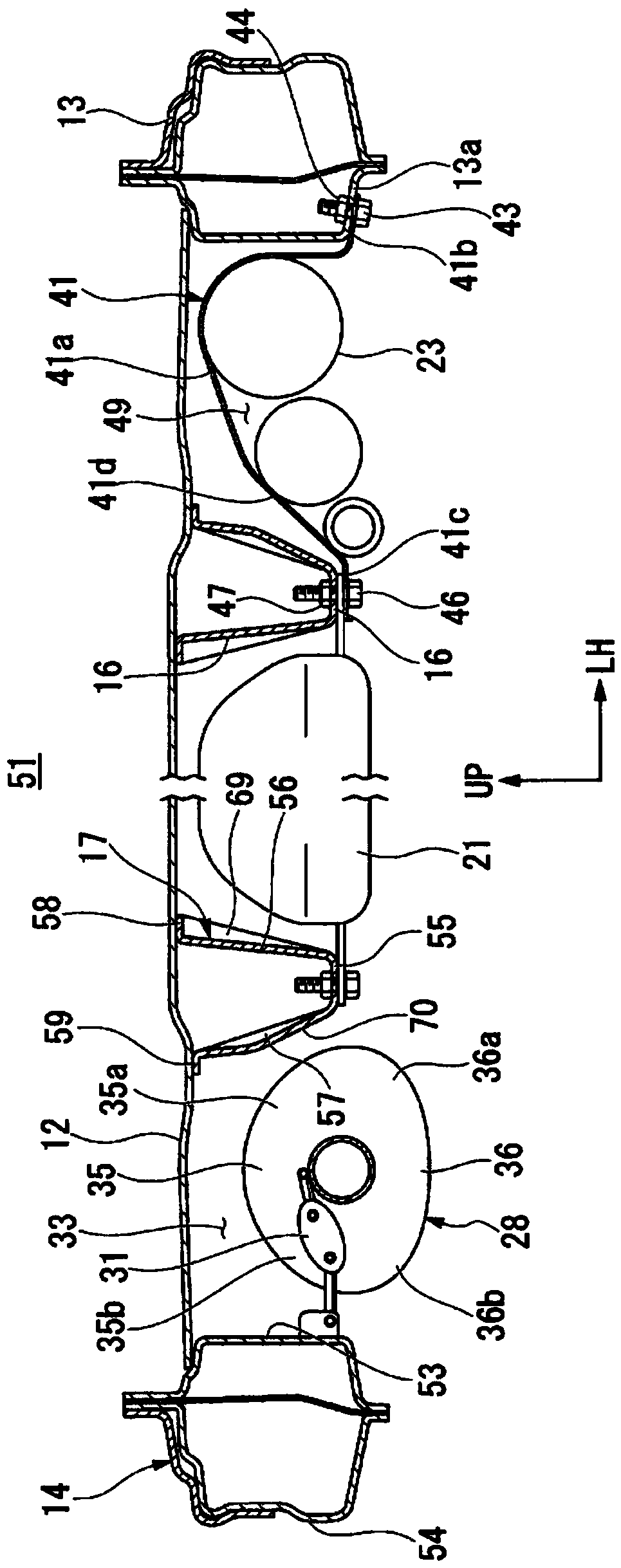
[0063] In addition, the vehicle body lower structure 10 includes a cross member 18 erected between the left side sill 13 and the right side sill 14 , a fuel tank 21 , an exhaust unit 22 , and a tank 23 .

[0064] The fuel tank 21 is provided in a region 25 below the floor panel 12 and in the center in the vehicle width direction. The area 25 is surrounded by the left floor frame 16, the right floor frame 17, and the beam 18 (specifically, the central beam 66). That is, the fuel tank 21 is provided on the inside of the left floor frame 16 in the vehicle width direction and on the inside of the right floor frame 17 in the...

no. 2 approach

[0161] The vehicle body lower structure 100 of the second embodiment will be described. In addition, in 2nd Embodiment, the same code|symbol is attached|subjected to the similar member same as 1st Embodiment, and detailed description is abbreviate|omitted.

[0162] Such as Figure 13 As shown, the vehicle body lower structure 100 assumes a state in which an in-vehicle component (muffler 28 ) is strongly sandwiched between the right side sill 102 and the right floor frame 17 .

[0163] In this case, the coefficient of friction of the inner side wall 103 of the right lower side sill 102 also needs to be considered.

[0164] The inner side wall 103 of the right side sill 102 has a predetermined coefficient of friction μ3. Therefore, when the impact load input to the right side sill 102 causes the upper deformation of the guide portion 77 (refer to Figure 9 (b)) In the upwardly deformed state, the muffler 28 is strongly sandwiched between the right side sill 102 and the right ...


PUM


Abstract

This structure for a lower portion of a vehicle body is provided with a right side sill (14), a right floor frame (17), a right cross member (68), and a muffler. A fuel tank is provided to the lateral-direction inner side of the right floor frame (17). The right cross member (68) extends in the lateral direction, spanning between the right floor frame (17) and the right side sill (14). The muffleris provided in an area enclosed by the right side sill (14), the right floor frame (17), and the right cross member (68). The right cross member (68) has an upward deformation guiding part (77). Theupward deformation guiding part (77) is formed so as to be capable of deforming upward due to an impact load (F2) inputted to the right side sill (14).

Description

technical field [0001] The present invention relates to vehicle body substructures. [0002] This application claims priority based on Japanese Patent Application No. 2016-125988 for which it applied on June 24, 2016, and uses the content here. Background technique [0003] As an underbody structure, there is known a structure in which beams extend from both sides of the floor tunnel toward the outside in the vehicle width direction to the side sill, and a beam member is provided inside the floor tunnel. The beam member is formed with a downward depression at the upper portion. Furthermore, a muffler (that is, an on-vehicle component) is arranged below the beam seat. Therefore, the beam member deforms downward due to the impact load input to the side sill, and the muffler can be pressed down through the beam member toward the floor tunnel. Accordingly, the floor tunnel can be deformed appropriately to absorb the impact load (for example, refer to Patent Document 1). [0...

Claims


Application Information

Patent Timeline
Patent Type & Authority Applications(China)
IPC IPC(8): B62D25/20B60K13/04
CPCB60K13/04B60K15/063B60K2015/0631B62D25/20
Inventor 加藤隆山根昌晃川边悟芳贺丈延安井健
Owner HONDA MOTOR CO LTD
Why Eureka
Try Eureka