A stepless speed control and energy clamping circuit of an alternating current motor and a device thereof

An AC motor, stepless speed regulation technology, applied in the field of circuits and devices, can solve the problem that AC motors are difficult to achieve stepless speed regulation, and achieve the effects of good control, reduction of electromagnetic interference, and improvement of efficiency

Pending Publication Date: 2018-12-21
SUZHOU LII SEMICON CO LTD
View PDF1 Cites 0 Cited by
  • Summary
  • Abstract
  • Description
  • Claims
  • Application Information

AI Technical Summary

Problems solved by technology

[0005] In order to overcome the defects in the prior art, the present invention provides a stepless speed regulation control and energy clamping circuit of an AC motor and its device, which solves the problem that the stepless speed regulation of an AC motor is difficult, and no longer needs any The speed control tap simplifies the motor structure, greatly reduces the cost, and realizes the stepless speed regulation on the cheap and mature traditional AC motor; at the same time, the energy clamp circuit is used to optimize the circuit performance, protect the system circuit from being damaged, and improve The energy conversion efficiency of the system ensures the practicality and safety of stepless speed regulation applications, and has broad market prospects

Method used


Image

  • A stepless speed control and energy clamping circuit of an alternating current motor and a device thereof
  • A stepless speed control and energy clamping circuit of an alternating current motor and a device thereof
  • A stepless speed control and energy clamping circuit of an alternating current motor and a device thereof

Examples


Embodiment Construction

[0021] The present invention is further illustrated below by means of examples, but the present invention is not limited to the scope of the examples.

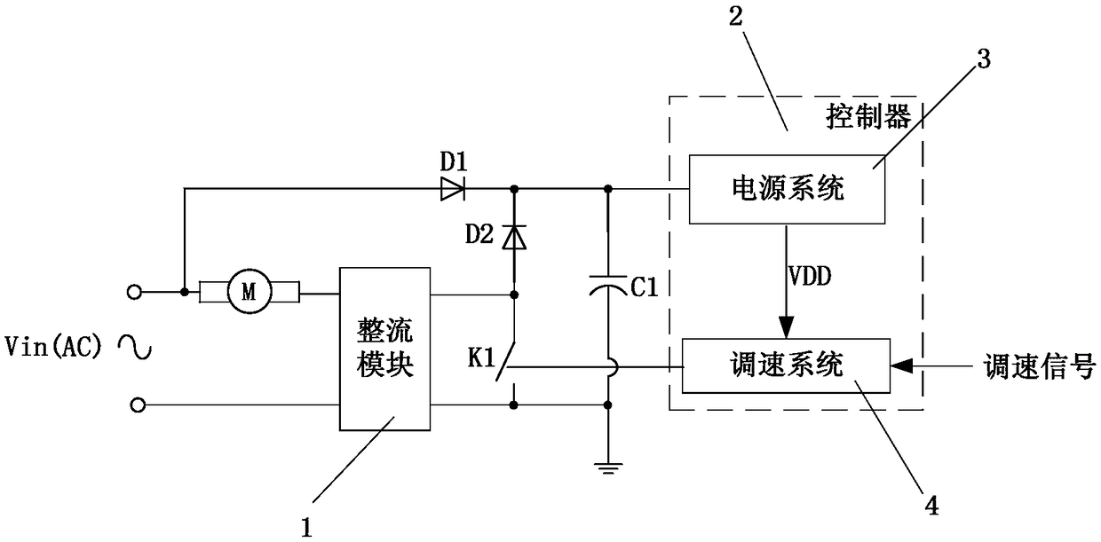
[0022] See figure 1 , a stepless speed regulation control and energy clamping circuit of an AC motor M in the present invention, comprising a rectifier module 1, a first diode D1, a second diode D2, a first capacitor C1, a three-wire power switch K1 and a control Device 2. The first diode D1 and the second diode D2 are used for providing an AC charging channel for the first capacitor C1, isolating reverse current, and introducing the reverse electromotive force of the AC motor into the first capacitor C1 to realize efficient energy conversion. The controller 2 is used to receive and output control signals to ensure the normal operation of the system and the stepless speed regulation of the AC motor. Preferably, the first capacitor C1 is a BULK capacitor. The controller 2 includes a power supply system 3 and a speed regulati...


PUM


Abstract

The invention discloses a stepless speed regulation control and energy clamping circuit of an alternating current motor and a device thereof, comprises a rectifier module, a first diode, a second diode, a first capacitor, a three-wire power switch and a controller, wherein the controller comprises a power supply system and a speed regulating system, a voltage input of the rectifier module is connected with a pole of an alternating current power supply, and a voltage input of the rectifier module is connected with one end of an alternating current motor. The invention solves the problem that the AC motor is difficult to realize the stepless speed regulation, no longer needs any speed regulation tap, simplifies the motor structure, greatly reduces the cost, and realizes the stepless speed regulation on the cheap and mature traditional AC motor. At the same time, the energy clamping circuit is used to optimize the circuit performance, protect the system circuit from damage, improve the system energy conversion efficiency, and ensure the application of stepless speed regulation practical and safe, which has broad market prospects.

Description

technical field [0001] The invention relates to a circuit and its device, in particular to a stepless speed regulation control and energy clamping circuit of an AC motor and its device. Background technique [0002] Traditional fan products such as floor fans, ceiling fans, desk fans, etc., use AC motors to convert AC electrical energy into mechanical energy. When it is necessary to adjust the fan speed, it is generally necessary to make the motor winding into a structure with multiple taps, so that it can be passed The switch switches different taps to adjust the speed. For example, the floor fan can be adjusted in high, medium and low speeds by using a piano key switch. [0003] At present, with the development of smart home appliances, fans have also become more multifunctional, and users have put forward more requirements for the functions of fans, such as wishing to have remote control functions, natural wind simulation functions, sleep wind simulation functions and net...

Claims


Application Information

Patent Timeline
Patent Type & Authority Applications(China)
IPC IPC(8): H02P23/28H02P27/04H02H9/04
CPCH02H9/042H02P23/28H02P27/04
Inventor 郑凌波周勇王福龙
Owner SUZHOU LII SEMICON CO LTD
Why Eureka
Try Eureka