Adaptive synchronous rectification control system and control method for active clamp flyback converter
A flyback converter and synchronous rectification technology, applied in control/regulation systems, DC power input conversion to DC power output, instruments, etc., can solve the problem of large body diode loss and the inability to improve the efficiency of active clamp flyback converters , Sampling resistance loss and other issues
- Summary
- Abstract
- Description
- Claims
- Application Information
AI Technical Summary
Problems solved by technology
Method used
Image
Examples
specific Embodiment 1
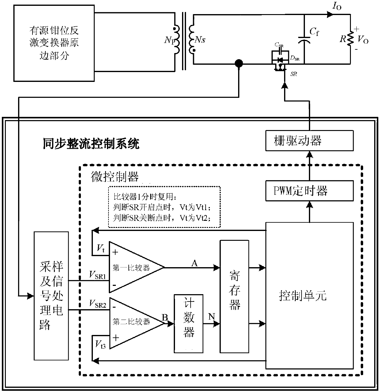
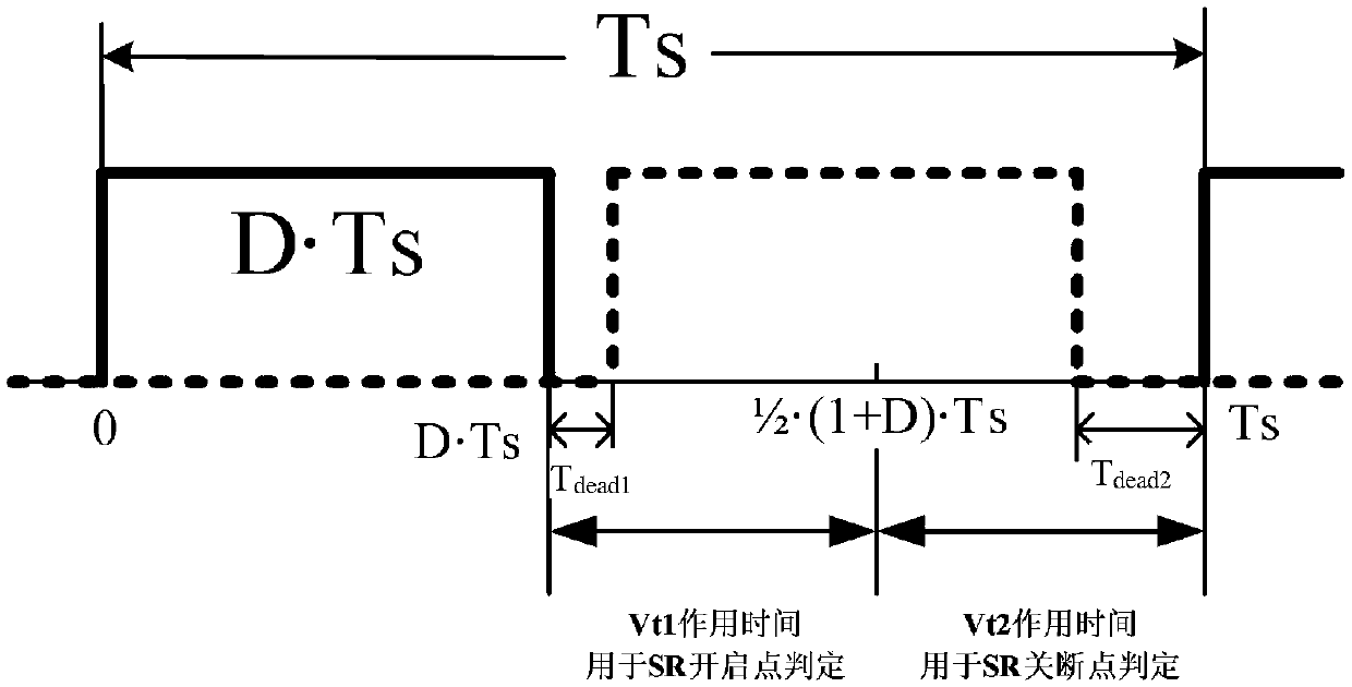
[0050] This embodiment combines image 3 the first threshold V on the non-inverting input of the first comparator t1 and the second threshold V t2 The schematic diagram of the action time period and the state detection time of the synchronous rectifier, and the technical scheme of the time-division multiplexing of the first comparator for the state detection of the synchronous rectifier is described in detail, as follows:
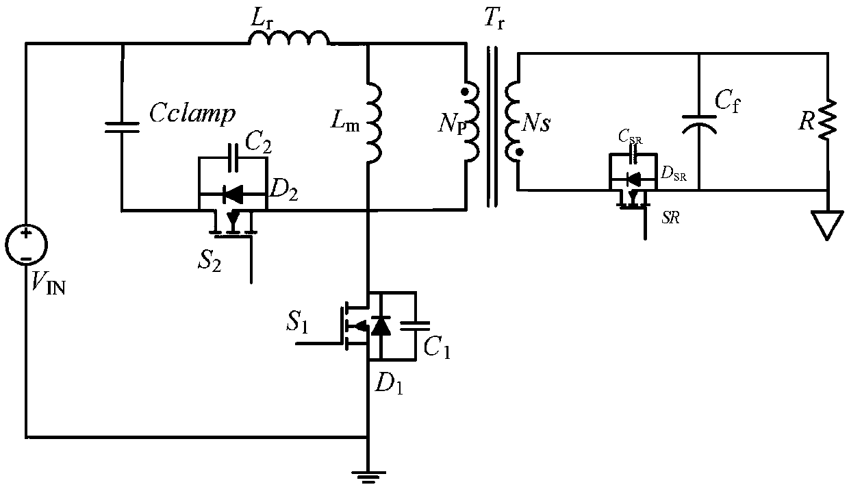
[0051] use figure 1 As shown in the active clamp flyback converter, define its primary side main power transistor S 1 The gate drive signal V gsThe duty cycle is D, and one duty cycle of the active clamp flyback converter is defined as T s , that is, the main power tube S 1 A duty cycle of T s , then the main power tube S 1 The conduction period is expressed as: T on =D×T s ; Main power tube S 1 The off-time period is expressed as: T off =(1-D)×T s . Primary side main power tube S 1 The gate drive signal V gs Such as image 3 As shown by the...
specific Embodiment 2
[0055] In this embodiment, the logic flow for detection and control of the on-state of the secondary synchronous rectifier when the primary side power tube of the active clamp flyback converter uses Si devices, and the primary side power tube of the active clamp flyback converter uses GaN devices The logic flow of the on-state detection and control of the synchronous rectifier tube on the secondary side is described in detail.
[0056] When the primary side power transistor of the active clamp flyback converter uses Si devices, in the current duty cycle During the time period, the logic flow of the detection and control of the on-state of the secondary synchronous rectifier is as follows: Figure 4 As shown, the details are as follows:
[0057] Step A-1. The control unit judges the clamping tube S on the primary side 2 Whether conduction: primary side clamp tube S 2 conduction, enter step A-2; the primary side clamp tube S 2 off, repeat step A-1;
[0058] Step A-2, prima...
specific Embodiment 3
[0069] This embodiment combines Image 6 , to carry out a detailed description of the off-state detection of the secondary side synchronous rectifier tube of the active clamp flyback converter and the control logic of the next cycle on-time, as follows:
[0070] Step C-1, in the current working cycle During the time period, the first sensing voltage V after the synchronous rectifier is turned off by using the first comparator SR1 and the second threshold V t2 Perform comparison and logic judgment: when the synchronous rectifier is turned off, the first sensing voltage signal V SR1 less than the second threshold V t2 , A is high level; the first sensing voltage signal V SR1 greater than the second threshold V t2 When , A is low level;
[0071] Step C-2, using the second comparator to turn off the second sensing voltage V after the synchronous rectifier is turned off SR2 and the third threshold V t3 Compare and output signal B: After the synchronous rectifier is turned ...
PUM
 Abstract
Description
Claims
Application Information
 - R&D
- Intellectual Property
- Life Sciences
- Materials
- Tech Scout
- Unparalleled Data Quality
- Higher Quality Content
- 60% Fewer Hallucinations
Browse by: Latest US Patents, China's latest patents, Technical Efficacy Thesaurus, Application Domain, Technology Topic, Popular Technical Reports.
© 2025 PatSnap. All rights reserved.Legal|Privacy policy|Modern Slavery Act Transparency Statement|Sitemap|About US| Contact US: help@patsnap.com


