
A monitoring system and method of a marine power station based on can bus

A technology for power station monitoring and ships, applied in electrical components, circuit devices, etc., can solve problems such as energy consumption, low sensitivity of current detectors, and low work efficiency

Inactive Publication Date: 2018-12-21
QINGDAO HUANGHAI UNIV
View PDF4 Cites 1 Cited by
  • Summary
  • Abstract
  • Description
  • Claims
  • Application Information

AI Technical Summary

Problems solved by technology

However, the communication of control instruments in the existing ship power station monitoring system is complicated and the flexibility is poor; at the same time, the utilization rate of the ship power station unit is low, consumes energy, and has low safety
[0003] To sum up, the problems existing in the existing technology are: the communication of the control instruments in the existing ship power station monitoring system is complicated and the flexibility is poor; at the same time, the utilization rate of the ship power station unit is low, energy consumption is low, and the safety is low
[0004] The sensitivity of the current detector in the prior art is low, and the accuracy of the detection data is poor; the data information such as the detected current, voltage, temperature, and short circuit state cannot be quantified and stored, and the anti-interference ability of the data information is poor, and it cannot be accumulated without noise. It is not conducive to the storage, processing and exchange of information; the display ability of the detection information in the existing technology is poor, which is not conducive to the reading of the data, and the grasp of the detection data is not timely, resulting in low work efficiency

Method used


Image

  • A monitoring system and method of a marine power station based on can bus
  • A monitoring system and method of a marine power station based on can bus
  • A monitoring system and method of a marine power station based on can bus

Examples


Embodiment Construction

[0074] In order to make the object, technical solution and advantages of the present invention more clear, the present invention will be further described in detail below in conjunction with the examples. It should be understood that the specific embodiments described here are only used to explain the present invention, not to limit the present invention.

[0075] The application principle of the present invention will be further described below in conjunction with the accompanying drawings and specific embodiments.

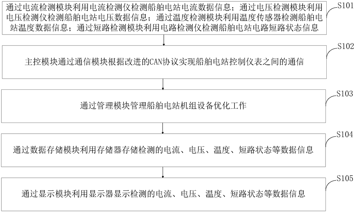
[0076] Such as figure 1 As shown, a kind of can bus-based ship power station monitoring method provided by the present invention comprises the following steps:

[0077] Step S101, using the current detector to detect the current data information of the ship power station through the current detection module; using the voltage detector to detect the voltage data information of the ship power station through the voltage detection module; using the temperature sens...


PUM


Abstract

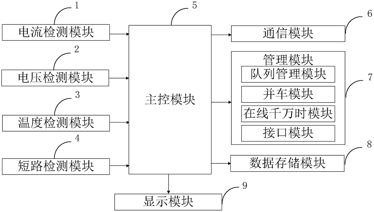
The invention belongs to the technical field of ship power station monitoring, discloses a marine power station monitoring system and method based on can bus. The marine power station monitoring system based on can bus comprises a current detection module, a voltage detection module, a temperature detection module, a short circuit detection module, a main control module, a communication module, amanagement module, a data storage module and a display module. The communication protocol of the intelligent control instrument based on the CAN bus through the communication module is simple in use,standardized in format and comprehensive in information, and together with the filter can be used as a broadcast or multicast address, which is very useful for improving the flexibility of communication; the communication protocol of the intelligent control instrument based on the CAN bus is simple in use, standardized in format and comprehensive in information. At the same time, it has wide practicability and strong market value. At the same time, through the management module, the utilization rate of the unit is improved, which can save energy, enhance the safe operation ability and reduce the operation cost.

Description

technical field [0001] The invention belongs to the technical field of ship power station monitoring, in particular to a can bus-based ship power station monitoring system and method. Background technique [0002] Ship power station refers to the device on the ship that converts mechanical energy into electrical energy and monitors, controls, measures, distributes and protects it. It consists of ship power supply, ship power network, power distribution system equipment and power system protection equipment. According to the power supply, it can be divided into main power supply (main generator set), emergency power supply (emergency generator set, battery pack, weak current power supply), auxiliary power supply (auxiliary generator set) and shore power box. The power distribution network can be divided into main power grid, emergency power grid, lighting power grid and weak power grid. Power distribution and protection equipment includes main distribution panel, emergency ...

Claims


Application Information

Patent Timeline
Patent Type & Authority Applications(China)
IPC IPC(8): H02J13/00
CPCH02J13/0062
Inventor 牛海春赵梅莲刘晓玲秦富贞李华光宋海燕杜友威
Owner QINGDAO HUANGHAI UNIV
Learn More