Concise light-emitting identifier
A luminous sign, a concise technology, applied in the field of advertising luminous signs and lighting, can solve the problems of the size of the luminous sign being too thick and the luminous effect is not uniform enough, etc.
- Summary
- Abstract
- Description
- Claims
- Application Information
AI Technical Summary
Problems solved by technology
Method used
Image
Examples
Embodiment 1
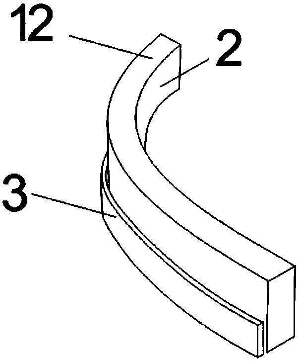
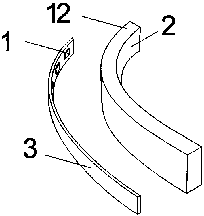
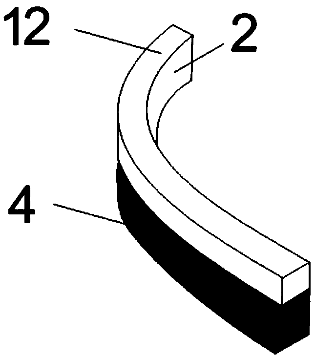
[0074] This embodiment discloses a simple luminous sign, refer to Figure 1A , Figure 1B , Figure 1C , Figure 1D and Figure 1E , which includes a light source and a light guide 2, wherein: the light source is a strip-shaped LED light source composed of several LED light sources 1 welded on a strip-shaped flexible circuit board 3, the light-emitting end surface 12 of the light guide 2 is a plane, and the light guide 2 is a translucent or foggy hard light-transmitting material with a rectangular cross-section, and the plate of this material is milled and carved according to the design pattern by a numerical control device; or the light guide 2 is made of a translucent or foggy rectangular cross-section The hard strip-shaped light-transmitting rubber strip is heated and bent according to the shape of the design pattern, and then cooled and shaped; or the light guide 2 is made of a semi-transparent or foggy flexible strip-shaped light-transmitting rubber strip , according t...
Embodiment 2
[0079] This embodiment discloses a simple luminous sign, refer to Figure 2A , Figure 2B , Figure 2C , which includes a light source and a light guide 2, wherein: the light source is a strip-shaped LED light source composed of several LED light sources 1 welded on a strip-shaped flexible circuit board 3, the light-emitting end surface 12 of the light guide 2 is a plane, and the light guide The longitudinal extension pattern of the light-emitting end surface of 2 is the letter "A". It is milled and carved, and a side accommodating groove 5 for accommodating a strip-shaped LED light source is processed at a part of the side wall of the light guide 2 near the bottom, so that each stroke of the "A"-shaped light guide 2 At least one side wall in the two side walls is provided with a side accommodating groove 5, the depth and width of the side accommodating groove 5 are respectively matched with the thickness and width of the strip-shaped LED light source (i.e. the width of the ...
Embodiment 3
[0084] Such as Figure 3A , Figure 3B , Figure 3C , Figure 3D As shown, the difference between this embodiment and Embodiment 1 and Embodiment 2 is that a bottom accommodating groove 8 for accommodating a strip-shaped LED light source is provided at the middle position of the bottom surface of the light guide body 2, and the depth of the bottom accommodating groove 8 and The width matches the width of the strip-shaped LED light source (i.e. the width of the circuit board 3) and twice the thickness, and two opposite strip-shaped LED light sources are placed in the bottom accommodation groove 8, and the two strip-shaped LED light sources The light emitting direction of the LED light source is respectively towards the two groove side walls perpendicular to the light-emitting end surface 12 of the light guide body 2 in the bottom accommodation groove 8; Figure 3B From the cross-sectional structure shown, it can be seen that there are four side walls of the light guide body ...
PUM
 Abstract
Description
Claims
Application Information
 - R&D
- Intellectual Property
- Life Sciences
- Materials
- Tech Scout
- Unparalleled Data Quality
- Higher Quality Content
- 60% Fewer Hallucinations
Browse by: Latest US Patents, China's latest patents, Technical Efficacy Thesaurus, Application Domain, Technology Topic, Popular Technical Reports.
© 2025 PatSnap. All rights reserved.Legal|Privacy policy|Modern Slavery Act Transparency Statement|Sitemap|About US| Contact US: help@patsnap.com


