
Automobile brake device

A technology of automobile brakes and automobiles, which is applied in the field of automobile brakes, and can solve problems such as shortening the service life of brake pads and brake discs, accelerating the wear speed of brake pads, and increasing the number of brake pads

Active Publication Date: 2018-12-21
上海八幡五金有限公司
View PDF5 Cites 9 Cited by
  • Summary
  • Abstract
  • Description
  • Claims
  • Application Information

AI Technical Summary

Problems solved by technology

[0002] At present, the traditional braking technology uses the hydraulic system to push the brake pads and brake discs to achieve the braking effect of the car; during the braking process, the brake pads as a whole always participate in the friction, and the ring-shaped area of ​​the brake disc and the brake pads is always frictional. No change; such a structure leads to severe local wear of the brake disc, faster overall wear of the brake pad, and increased frequency of replacement of the brake pad, thereby seriously shortening the service life of the brake pad and brake disc, and increasing the maintenance cost of the vehicle

Method used


Image

  • Automobile brake device
  • Automobile brake device
  • Automobile brake device

Examples


specific Embodiment approach

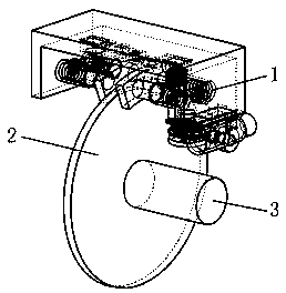
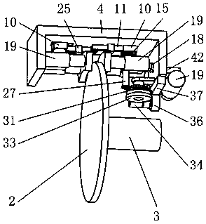
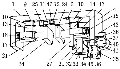
[0056] The specific embodiment: when the automobile does not need to brake, the driver does not step on the brake pedal, and the brake pad 24 is positioned at the initial position and does not move;

[0057] When the car in the driving state brakes normally, the driver slowly steps on the brake pedal; the brake pedal activates the vacuum booster; the vacuum booster controls the operation of the brake master cylinder, so that the hydraulic oil enters the hydraulic pressure instantaneously under the action of pressure. Cylinder 41; the hydraulic oil in the hydraulic cylinder 41 pushes the hydraulic column 40 to slide outside the hydraulic cylinder 41; the hydraulic column 40 drives the worm 34 to rotate through the third connecting block 39, the rack, the gear and the second shaft 35; the worm 34 drives the worm gear 33 rotation; the worm wheel 33 drives the tapered thread drive wheel 31 to rotate through the first shaft 32; the star wheel 28 moves relative to the tapered thread ...


PUM


Abstract

The invention belongs to the automobile brake field, in particular to an automobile brake device, which comprises a brake mechanism, a brake disc and a wheel axle, wherein the brake disc is mounted onone end of the wheel axle of the automobile; The brake mechanism is fixedly installed on the vehicle body, and the brake mechanism is matched with the brake disc; During the braking process, the contact area between the brake pads and the brake discs increases, which decreases the friction force per unit area on the friction surface between the brake pads and the brake discs, effectively controlsthe wear of the brake pads and the brake discs, and further prolongs the service life of the brake pads and the brake discs. During the braking process, two brake pads of the two brake pad mechanismsrespectively contact with two end faces of the brake disc and generate friction, so that the forces on the two end faces of the brake disc are balanced, the damage of the brake disc caused by long-term unilateral force is avoided, the brake disc replacement cycle is delayed, and the maintenance cost of the brake system of the automobile is reduced.

Description

technical field [0001] The invention belongs to the field of automobile brakes, in particular to an automobile brake device. Background technique [0002] At present, the traditional braking technology uses the hydraulic system to push the brake pads and brake discs to achieve the braking effect of the car; during the braking process, the brake pads as a whole always participate in the friction, and the ring-shaped area of ​​the brake disc and the brake pads is always frictional. No change; such a structure leads to serious local wear of the brake disc, faster overall wear of the brake pads, and increased frequency of replacement of the brake pads, thereby seriously shortening the service life of the brake pads and brake discs, and increasing the maintenance cost of the vehicle. [0003] The present invention designs an automobile braking device to solve the above problems. Contents of the invention [0004] In order to solve the above-mentioned defects in the prior art, ...

Claims


Application Information

Patent Timeline
Patent Type & Authority Applications(China)
IPC IPC(8): B60T1/06B60T13/52B60T13/74
CPCB60T1/065B60T13/12B60T13/52
Inventor 李华炜李华鸿
Owner 上海八幡五金有限公司
Learn More