Inner hole automatic chamfering device

A chamfering device and automatic technology, which is applied to the field of automatic chamfering devices for inner holes, can solve the problems of difficult application of gears, disassembly, low practical applicability, etc., and achieves the effect of improving applicability and simple operation.

Pending Publication Date: 2018-12-21
ZHONGSHAN UNIVERSAL ENTERPRISE LTD
View PDF1 Cites 1 Cited by
  • Summary
  • Abstract
  • Description
  • Claims
  • Application Information

AI Technical Summary

Problems solved by technology

However, the chamfering drill of this chamfering machine is composed of a drill body and a drill handle, and the drill body and the drill handle are of an integrated structure, and the drill handle is connected with the output shaft of the geared motor. It is inconvenient to replace the chamfering drill after being disassembled from the top, which makes it difficult for the chamfering machine to be suitable for gears with different inner hole sizes, and the practical applicability is low

Method used


Image

  • Inner hole automatic chamfering device
  • Inner hole automatic chamfering device
  • Inner hole automatic chamfering device

Examples


Embodiment Construction

[0021] The following will clearly and completely describe the technical solutions in the embodiments of the present invention with reference to the accompanying drawings in the embodiments of the present invention. Obviously, the described embodiments are only some, not all, embodiments of the present invention. Based on the embodiments of the present invention, all other embodiments obtained by persons of ordinary skill in the art without making creative efforts belong to the protection scope of the present invention.

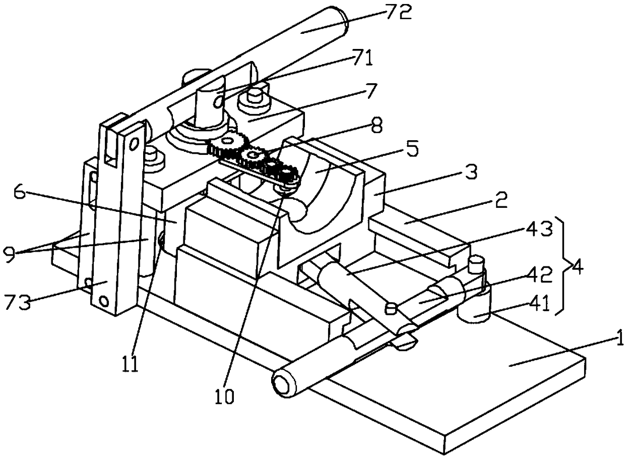
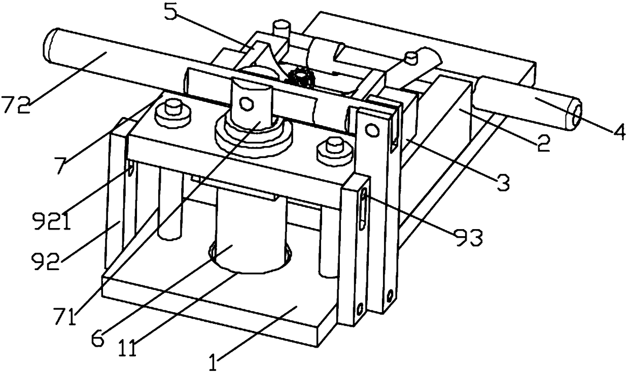
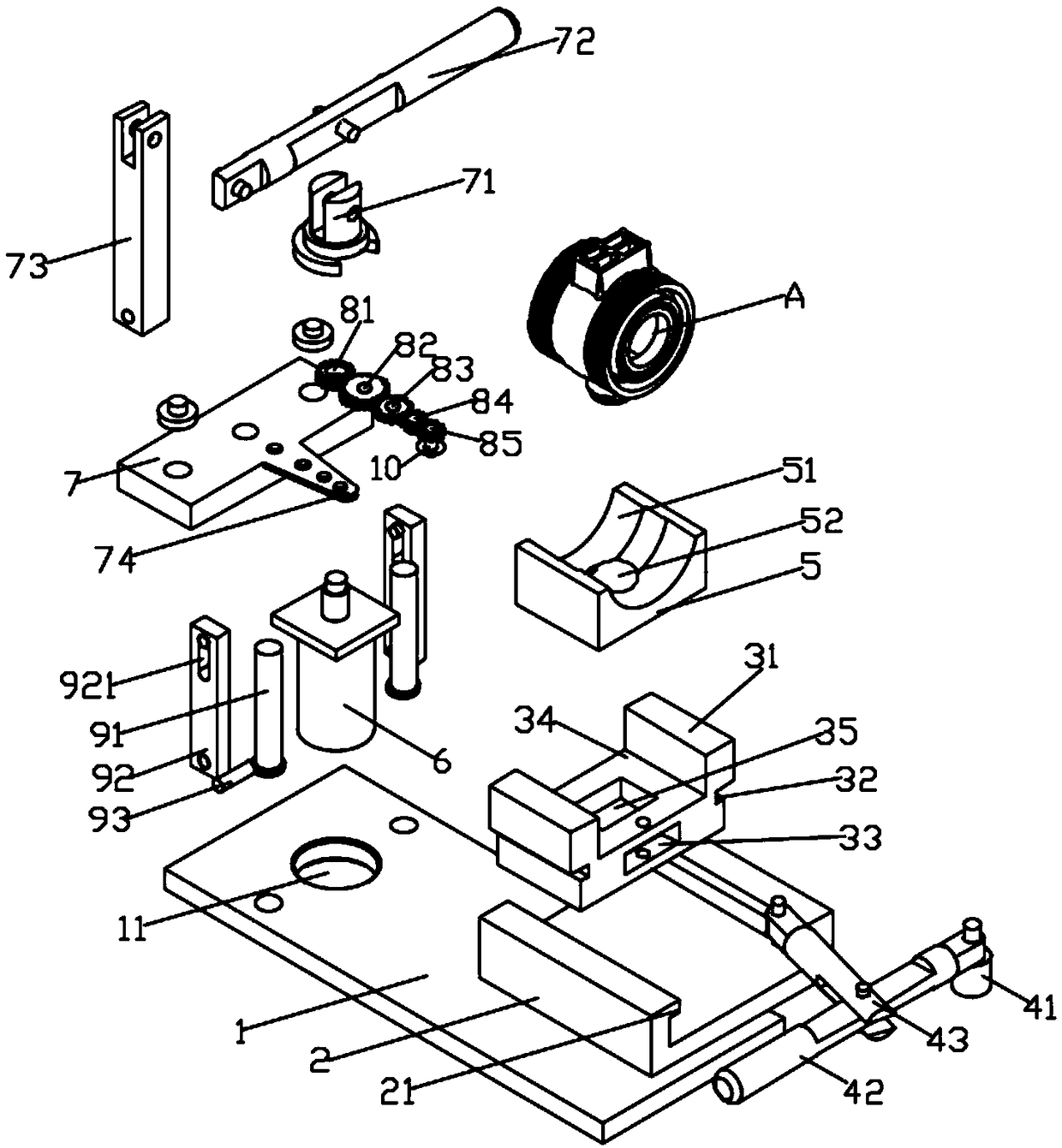
[0022] Such as Figure 1-Figure 4 Shown is a structural schematic diagram of an embodiment of an automatic inner hole chamfering device provided by the present invention: it includes a bottom plate 1, a fixing seat 2 is installed on the bottom plate 1, slide rails 21 are respectively arranged on both sides of the fixing seat 2, and a The mold cavity base 3, the mold cavity base 3 includes a mold cavity base body 31, the two sides of the mold cavity base body 3...


PUM


Abstract

The invention discloses an inner hole automatic chamfering device. The inner hole automatic chamfering device comprises a base plate; a fixed base is mounted on the base plate; a mold cavity base is mounted on the fixed base; the mold cavity base is connected with a rocking rod module for driving the mold cavity base to move; a mold cavity is mounted on the mold cavity base; a through hole is formed in the base plate, and is provided with a motor; a gear positioning plate is arranged above the motor; a gear set is mounted on the gear positioning plate; an output shaft of the motor penetrates through the gear positioning plate, and is connected with the gear set; the gear positioning plate is mounted on a support column module; the support column module is connected with the base plate; a detachable chamfering blade is mounted on the gear set; and the chamfering blade is positioned above the mold cavity. The inner hole automatic chamfering device is simple in operation and convenient touse, and can be suitable for machined parts with multiple inner hole diameters.

Description

technical field [0001] The invention relates to the technical field of chamfering equipment, in particular to an automatic chamfering device for inner holes. Background technique [0002] The purpose of chamfering parts is to remove burrs caused by processing on parts, and to facilitate the assembly of parts and improve the overall aesthetics of parts. The traditional chamfering method is to use manual chamfering, which is inefficient and accurate. , in order to improve production efficiency, automatic equipment is used for chamfering, but the applicability of existing automatic chamfering equipment is not high. The angle machine includes a working surface and legs for supporting the working surface, a motor and a reducer are fixedly installed on the working surface; the output shaft of the motor is provided with a drive wheel, and the input shaft of the reducer is provided with There is a driven wheel, and the driving wheel and the driven wheel are connected by a belt; a c...

Claims


Application Information

Patent Timeline
IPC IPC(8): B23D79/00
CPCB23D79/00
Inventor 方景辉冯国途岑接文李伟高明
Owner ZHONGSHAN UNIVERSAL ENTERPRISE LTD
Why Eureka
Try Eureka