A stabilizer for suppressing power oscillation of a flexible DC power transmission system

A power transmission system, flexible DC technology, applied in the direction of reducing/preventing power oscillation, AC network circuits, circuit devices, etc., can solve the problems of poor control effect and insufficient stable active power, so as to suppress power oscillation and improve fast Sexuality and accuracy, the effect of improving accuracy

Active Publication Date: 2018-12-18
HUAZHONG UNIV OF SCI & TECH +1
View PDF5 Cites 9 Cited by
  • Summary
  • Abstract
  • Description
  • Claims
  • Application Information

AI Technical Summary

Problems solved by technology

When the wind turbine is connected to the flexible DC transmission system, the system will have power oscillations of various frequencies. In addition to sub-synchronous oscillations, low-frequency oscillations and super-synchronous oscillations may also occur. Sub-synchronous damping control faces oscillations at other frequencies, and the control effect will be reduced. become worse, not enough to achieve the purpose of stabilizing active power

Method used


Image

  • A stabilizer for suppressing power oscillation of a flexible DC power transmission system
  • A stabilizer for suppressing power oscillation of a flexible DC power transmission system
  • A stabilizer for suppressing power oscillation of a flexible DC power transmission system

Examples


Embodiment Construction

[0029] The present invention is a control method and system for suppressing active power oscillation of a flexible direct current transmission system. The present invention will be further described in detail below in conjunction with the accompanying drawings and embodiments. It should be understood that the specific embodiments described here are only used to explain the present invention, not to limit the present invention.

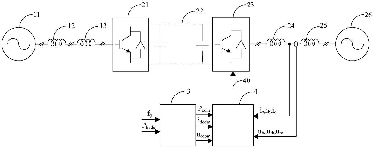
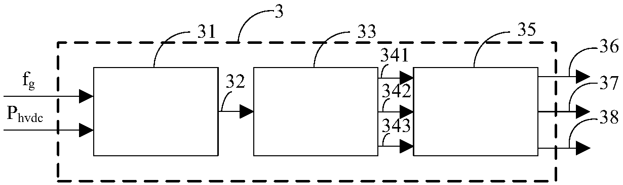
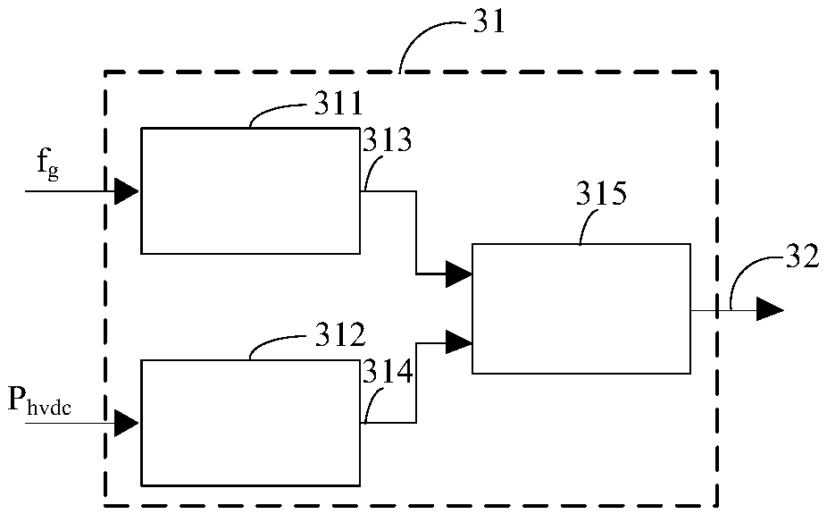
[0030] figure 1 It is a schematic diagram of the overall principle of the power oscillation stabilizer according to the present invention. Such as figure 1As shown in , the application object of the power oscillation stabilizer according to the present invention is, for example, a flexible direct current transmission system. As is well known in the art, the flexible direct current transmission system includes: a sending-end AC grid 11, a sending-end line equivalent impedance 12, The sending-end flexible DC converter station filter regulator 13 for fi...


PUM


Abstract

A stabilizer for suppressing power oscillation of a flexible DC power transmission system is disclosed, and the stabilizer includes a compensation command generator and a converter station controller,the compensation command generator collects the active power signals from the frequency of the power network and the output of the flexible DC power transmission system, and forms the compensation signal of the active power command value, the compensation signal of the d-axis current command value and the compensation signal of the d-axis output voltage through the calculation and processing, andoutputs the three compensation signals to the converter station controller at the same time; the converter station controller collects the three-phase output current and three-phase terminal voltagesignals of the flexible DC power transmission system, combines the received active power command value compensation signal, d-axis current command value compensation signal and d-axis output voltage compensation signal, and generates the driving signal of the converter station through calculation and processing. Through the invention, the small-signal stability of the flexible DC power transmission system can be effectively enhanced.

Description

technical field [0001] The invention relates to the field of flexible direct current transmission, and more particularly, to a stabilizer for suppressing power oscillation of a flexible direct current transmission system. Background technique [0002] The flexible HVDC system mainly includes the flexible DC converter station at the sending end, the DC transmission line for transmitting DC power, and the flexible DC converter station at the receiving end. Among them, the stability of the active power of the flexible DC transmission system is realized by controlling the flexible DC converter station, and this method is widely used. In this method, the difference between the active power reference signal and the active power detection signal is generated through the active power controller to generate the d-axis current reference signal. The difference between the d-axis current reference signal and the d-axis current detection signal is generated, and the d-axis output voltag...

Claims


Application Information

Patent Timeline
Patent Type & Authority Applications(China)
IPC IPC(8): H02J3/24H02J3/36
CPCH02J3/24H02J3/36H02J2003/365Y02E60/60
Inventor 胡家兵黄云辉朱建行刘栋胡祥楠翟雪冰寇龙泽谷怀广闫鹤鸣
Owner HUAZHONG UNIV OF SCI & TECH
Why Eureka
Try Eureka