
Cross layout antenna deployment device applied to spacecraft

A spacecraft and antenna technology, applied in the field of spacecraft accessories, can solve the problems of the overall weight of the system, the weight of the spacecraft and the limitation of the outer envelope, and the occupation of the mounting surface of the spacecraft load, so as to achieve light weight, small envelope, Overall compact effect

Active Publication Date: 2020-08-11
SHANGHAI SATELLITE ENG INST
View PDF8 Cites 0 Cited by
  • Summary
  • Abstract
  • Description
  • Claims
  • Application Information

AI Technical Summary

Problems solved by technology

The traditional antenna deployment device mainly uses one antenna to configure one deployment device. If multiple antennas are arrayed, multiple deployment devices are required. Although the structure is simple, the overall weight of the system is heavy and occupies a limited load mounting area on the surface of the spacecraft.
Especially for tiny spacecraft, there are strict restrictions on the weight and outer envelope of the spacecraft

Method used


Image

  • Cross layout antenna deployment device applied to spacecraft
  • Cross layout antenna deployment device applied to spacecraft
  • Cross layout antenna deployment device applied to spacecraft

Examples


Embodiment Construction

[0033] The present invention will be described in detail below in conjunction with specific embodiments. The following examples will help those skilled in the art to further understand the present invention, but do not limit the present invention in any form. It should be noted that those skilled in the art can make several changes and improvements without departing from the concept of the present invention. These all belong to the protection scope of the present invention.

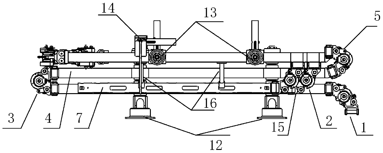
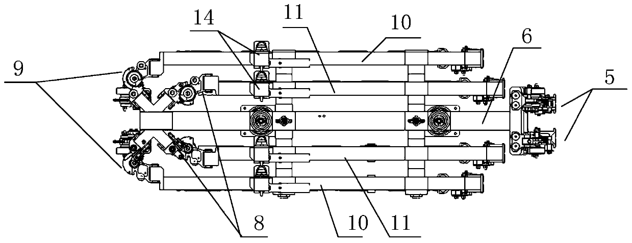
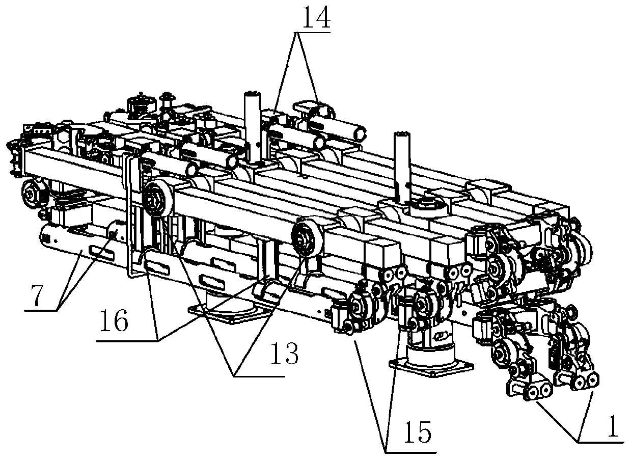
[0034] Such as Figure 1 to Figure 14 As shown, the present invention provides a cross layout antenna deploying device applied to spacecraft, including root hinge 1, No. 1 main extension arm 2, hinge 3 between No. 1 poles, No. 2 main extension arm 4, and No. 2 inter-pole Hinge 5, No. 3 main extension arm 6, 4 antennas 7, 45° deployment hinge 8, 135° deployment hinge 9, 2 inner antenna installation arms 10, 2 outer antenna installation arms 11, main extension arm compression release device 12. Antenna i...


PUM


Abstract

The invention discloses a cross-layout antenna deployment device applied to a spacecraft, which includes a root hinge, Main extension arm one, Hinge between poles one, Main extension arm number two, hinge between two rods, Main extension arm number three, 4 antennas, 45 deg. Deployment hinge, 135 deg. Deployment hinge, two inn antenna mounting arm, two outer antenna mounting arms, a main extensionarm pressure release device, an antenna mount arm pressure release device, an antenna bundle unlocking device, an antenna deployment hinge and an antenna support, the inner antenna mounting arm beingconnected with an X-shaped joint through the 45 deg. Deployment hinge; The outer antenna mounting arm is connected with an X-shaped joint through a 135-degree deployment hinge. The invention can effectively fold the four cross-layout antennas to a smaller envelope, reasonably arrange the pressing points, so that the folded state not only meets the requirements of the rocket envelope, but also meets the requirements of the mechanical conditions of the active section. After entering orbit, the antenna can be unlocked and deployed to the specified position according to the remote control commandand meet the requirements of antenna cross layout.

Description

technical field [0001] The invention relates to the field of spacecraft accessories, in particular to a cross layout antenna deployment device applied to spacecraft. Background technique [0002] With the development of aerospace technology, the spacecraft has higher and higher requirements for the antenna load capacity, and the antenna load usually needs to work through multiple antenna arrays to meet the performance requirements. And many antennas need to be extended to a position away from the spacecraft body to avoid electromagnetic interference of the spacecraft body or interference with other spacecraft loads. The traditional antenna deployment device mainly uses one antenna to configure one deployment device. If multiple antennas are arrayed, multiple deployment devices are required. Although the structure is simple, the overall weight of the system is heavy, and the limited load mounting area on the surface of the spacecraft is occupied. Especially for tiny spacecra...

Claims


Application Information

Patent Timeline
Patent Type & Authority Patents(China)
IPC IPC(8): H01Q1/08H01Q1/12H01Q1/36H01Q3/02H01Q21/00
CPCH01Q1/08H01Q1/1235H01Q1/36H01Q3/02H01Q21/00
Inventor 聂斌斌顾志悦杨铭波赵枝凯袁野
Owner SHANGHAI SATELLITE ENG INST
Learn More