
A production line design visualization system based on VR technology

A production line and technology technology, applied in the field of virtual reality, can solve problems such as customer dissatisfaction, reduced work efficiency, communication barriers, etc., to achieve the effect of improving design efficiency, achieving effective communication, and increasing a sense of identity

Pending Publication Date: 2018-12-18
CHINA AVIATION PLANNING & DESIGN INST GRP
View PDF7 Cites 5 Cited by
  • Summary
  • Abstract
  • Description
  • Claims
  • Application Information

AI Technical Summary

Problems solved by technology

The traditional method of carrying out production line design is CAD two-dimensional design. The defect of this method is that the design process lacks a sense of space. Problems such as "running, leakage, collision, and lack" are not clearly reflected on the design drawings, and the communication between designers and customers is not intuitive enough. , There are often deviations in the understanding of customer needs, which leads to repeated revisions in the design process and reduces work efficiency
[0003] At present, two-dimensional design has been gradually replaced by three-dimensional design methods, and the production line design is carried out in the form of three-dimensional modeling, which solves the problem of lack of "sense of space" in the scheme design. However, there are still communication barriers in the process of communicating with customers, such as : What the designer gives to the customer is the 3D model rendering and animation of the design process. The customer is in a state of passively accepting information, and the details that they really want to know may not be included in the existing materials, resulting in customer dissatisfaction after the production line is completed. situation, the transformation will generate a lot of waste of manpower and material resources

Method used


Image

  • A production line design visualization system based on VR technology
  • A production line design visualization system based on VR technology

Examples


Embodiment Construction

[0020] Exemplary embodiments of the present disclosure will be described in more detail below with reference to the accompanying drawings. Although exemplary embodiments of the present disclosure are shown in the drawings, it should be understood that the present disclosure may be embodied in various forms and should not be limited by the embodiments set forth herein. Rather, these embodiments are provided for more thorough understanding of the present disclosure and to fully convey the scope of the present disclosure to those skilled in the art.

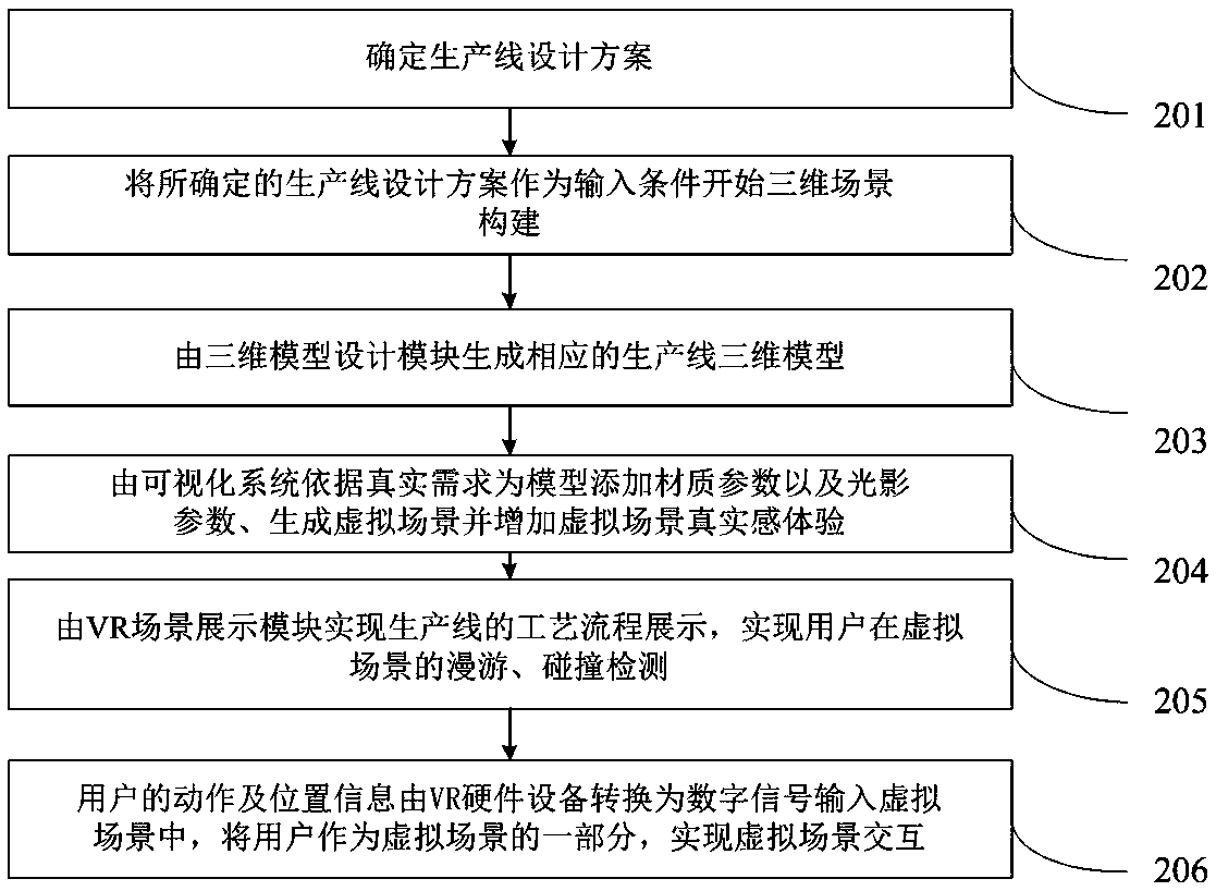
[0021] figure 1 It is a block diagram of a production line design visualization system based on VR technology according to an embodiment of the present invention. As shown in the figure, the production line design visualization system 101 based on VR technology includes: a three-dimensional model design module 102 , a VR scene display module 103 and a VR hardware device module 104 . in,

[0022] Among them, the 3D model design mo...


PUM


Abstract

The invention provides a production line design visualization system based on VR technology, comprising: a three-dimensional model design module, which is used for three-dimensional modeling of buildings, structures, equipment facilities, personnel and materials in the production line design, completing light shadow design, completing material rendering, and constructing a three-dimensional virtual scene of the production line; a VR scene display module, which is used for visualizing the production line design and realizing the observation of the virtual scene, the movement in the virtual scene and the collision detection in the production line three-dimensional virtual scene formed by the three-dimensional model design module; and a VR hardware device module, which is used for displayingthe virtual scene and locating the position and action of the person in the virtual scene, and transmitting the corresponding data to the VR scene display module. The production line design visualization system of the invention has strong immersion feeling; with the help of collision detection function, the rationality of operator position design and logistics channel design can be evaluated, which provides data support for further optimization of production line design.

Description

technical field [0001] The invention relates to the field of virtual reality technology, in particular to a production line design visualization system based on VR technology. Background technique [0002] Virtual Reality (VR for short) technology is a computer simulation system that can create and experience a virtual world. It uses a computer to generate a simulated environment, allowing users to immerse themselves in this environment to realize the interaction between humans and the virtual world. At present, VR technology has been widely used in many fields such as military aerospace, interior design, medical education, entertainment games, urban planning, and cultural relics protection. The traditional method of carrying out production line design is CAD two-dimensional design. The defect of this method is that the design process lacks a sense of space. Problems such as "running, leakage, collision, and lack" are not clearly reflected on the design drawings, and the c...

Claims


Application Information

Patent Timeline
Patent Type & Authority Applications(China)
IPC IPC(8): G06F17/50G06T19/00
CPCG06T19/006G06F30/20
Inventor 李金芝
Owner CHINA AVIATION PLANNING & DESIGN INST GRP
Learn More