Vibration attenuation structure and compressor provided with same
A vibration-damping structure and compressor technology, which is applied in the field of compressors, can solve problems such as compressor vibration and noise, and achieve the effects of suppressing resonance, reducing vibration and noise, and widening the operating frequency and working condition range
- Summary
- Abstract
- Description
- Claims
- Application Information
AI Technical Summary
Problems solved by technology
Method used
Image
Examples
Embodiment 1
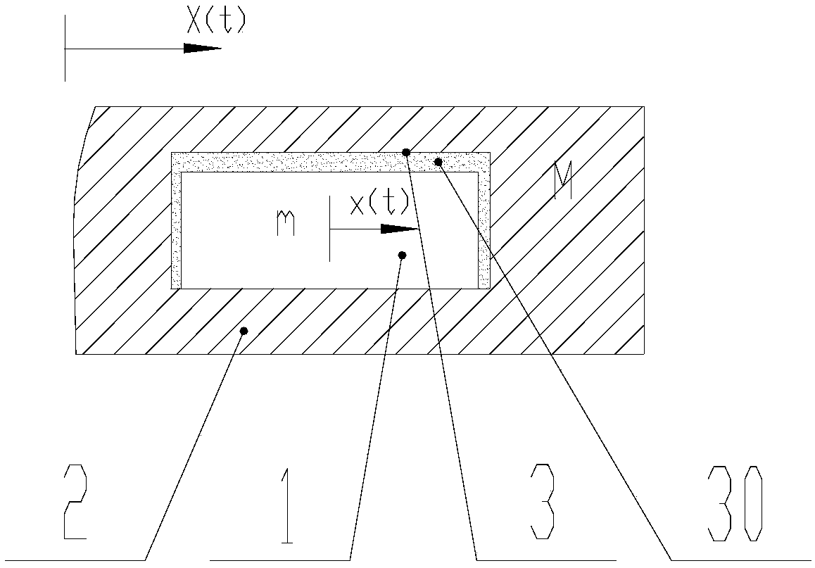
[0110] Embodiment 1 Referring to Figures 3 and 4, preferably, the vibrating body includes the cylinder 7, and a cylinder hole 71 is arranged on the cylinder 7 along the axial direction, and the cylinder hole 71 is formed as the cavity Part or all of the mass block 1 is arranged in the cylinder bore 71 . The mass block and the cavity can be used to reduce vibration and noise of the cylinder.
[0111] Preferably, the cylinder hole 71 is a circular through hole passing through the cylinder 7 along the axial direction, and the mass block 1 is a cylindrical structure.
[0112] Preferably, the bearing 8 includes a first bearing 81 connected to one axial end surface of the cylinder 7 and a second bearing 82 connected to the other axial end surface of the cylinder 7, the first bearing 81 and The second bearing 82 seals the circular through hole into the airtight cavity.
[0113] Preferably, the axial gap e3 between the proof mass 1 and the cavity satisfies 0<e3<2mm, and the radial gap...
Embodiment 2
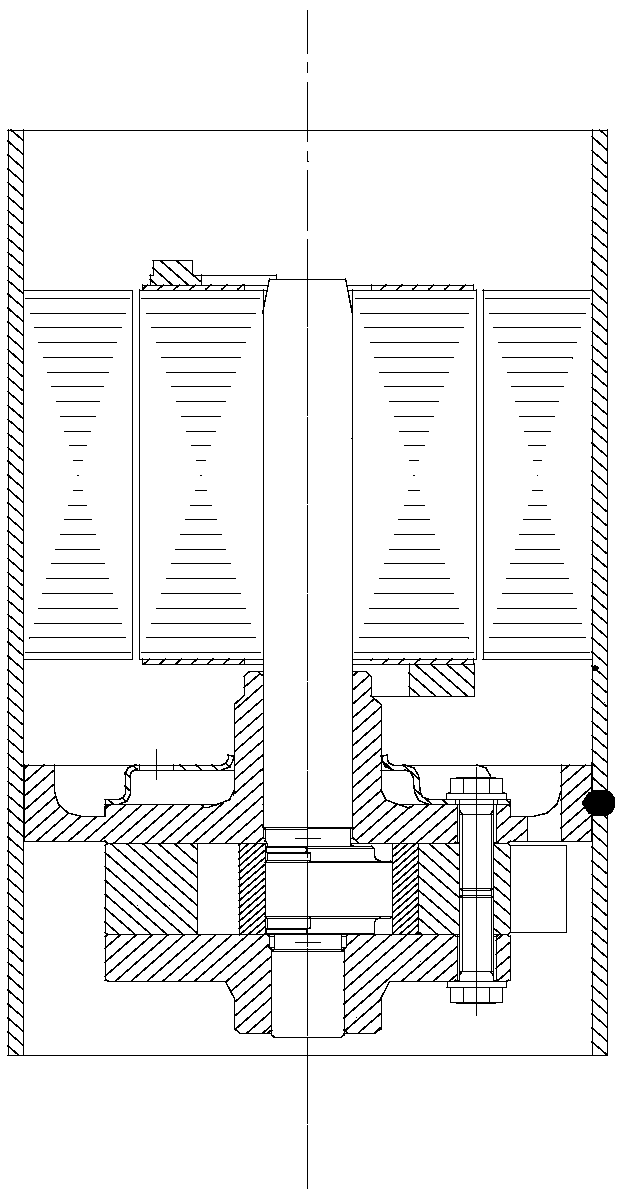
[0118] Example 2, see Figure 5 , preferably, the vibrating body includes a crankshaft 5, and a crankshaft hole 51 is provided at one end of the crankshaft 5 along its axial direction, the crankshaft hole 51 forms part or all of the cavity, and the mass 1 is set in the crankshaft hole 51. The mass block and the cavity can be used to reduce vibration and noise of the crankshaft.
[0119] Preferably, a screw 9 is inserted into the crank hole 51 at the one end of the crankshaft 5, and the crank hole 51 is sealed into an airtight cavity through the screw 9; Figure 5 , in Embodiment 2 of the present invention, the airtight cavity 3 is composed of a cylindrical hole 13 and a screw 14 sealed at the upper end of the crankshaft 12; the axial (Z-direction) gap e3 between the cylindrical mass 1b and the airtight cavity 3 satisfies (0<e3<2mm), the radial clearance e1,2 satisfies (0<e1,2<2mm).
[0120] A modified embodiment of Embodiment 2, or, the compressor further includes a rotor u...
Embodiment 3
[0122] Example 3, see Figure 7 ,Preferably,
[0123] Described vibrating body comprises described crankshaft 5 and motor rotor 6, and described crankshaft 5 is arranged in the inner hole of described motor rotor 6, and also comprises rotor upper baffle plate 10, and one end of described crankshaft 5 is connected with described rotor. There is a gap between the baffles 10 , and the gap between the one end of the crankshaft 5 and the upper baffle 10 of the rotor forms the airtight cavity. The mass block and the cavity can be used to jointly reduce the vibration and noise of the crankshaft and the motor rotor.
[0124] Preferably,
[0125] The gap is a cylindrical hole, the mass block 1 is a cylinder, and the axial gap e3 between the mass block 1 and the cavity satisfies 0
[0126] combined with Figure 7 In Embodiment 3 of the present invention, the airtight cavity 3 is composed of the upper end surface of the cranksha...
PUM
 Abstract
Description
Claims
Application Information
 - R&D Engineer
- R&D Manager
- IP Professional
- Industry Leading Data Capabilities
- Powerful AI technology
- Patent DNA Extraction
Browse by: Latest US Patents, China's latest patents, Technical Efficacy Thesaurus, Application Domain, Technology Topic, Popular Technical Reports.
© 2024 PatSnap. All rights reserved.Legal|Privacy policy|Modern Slavery Act Transparency Statement|Sitemap|About US| Contact US: help@patsnap.com


