
Gas distribution system of engine, and engine

A technology of engine and active gear, which is applied in the direction of engine components, machines/engines, mechanical equipment, etc., can solve the problems of increased engine operating noise, changes in the matching relationship of components, and affecting the service life of components, etc., achieving a simple and compact structure, avoiding The effect of loose installation

Pending Publication Date: 2018-12-18
CHONGQING LONCIN ENGINE +1
View PDF0 Cites 0 Cited by
  • Summary
  • Abstract
  • Description
  • Claims
  • Application Information

AI Technical Summary

Problems solved by technology

[0003] However, the cooperation between the aluminum alloy cylinder head and other parts of the engine will have a series of problems. For example, the gas distribution system, from the timing drive gear to the rocker arm, will deform at high temperatures, which will increase the operating noise of the entire engine. Moreover, thermal deformation will also lead to changes in the matching relationship of components, which will affect the service life of components
In the prior art, the timing driving gear in the gas distribution system cooperates with the crankshaft transmission, the thermal deformation of the crankshaft and the thermal deformation of the gear itself will cause the shape of the timing driving gear to change, and the meshing relationship with the driven gear will change Well, resulting in noise and a decrease in service life, and greater noise will also affect the environmental performance of the engine

Method used


Image

  • Gas distribution system of engine, and engine
  • Gas distribution system of engine, and engine
  • Gas distribution system of engine, and engine

Examples


Embodiment Construction

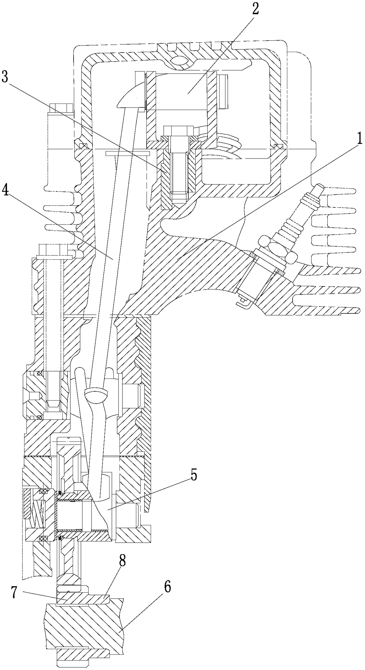
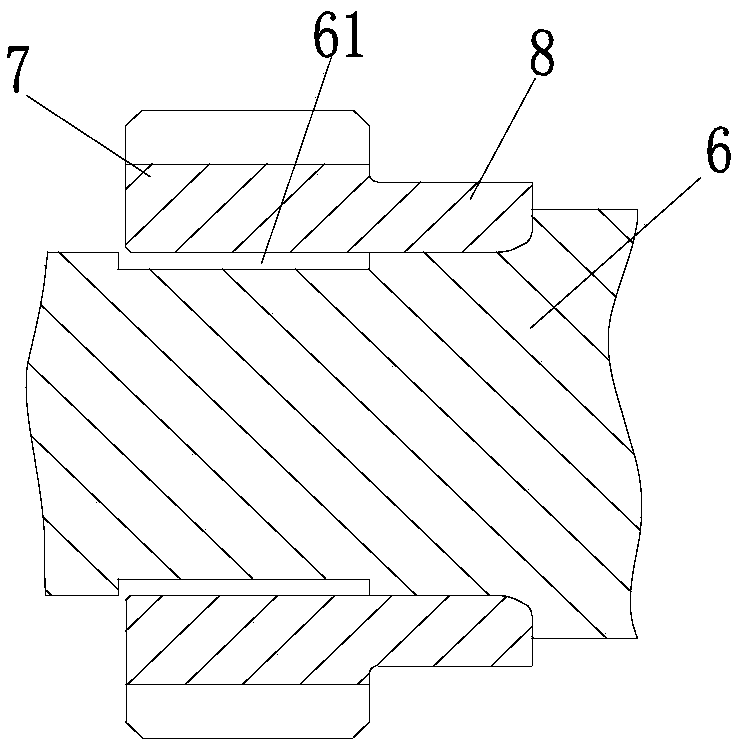
[0023] As shown in the figure: the engine gas distribution system of the present embodiment, the timing driving gear of the gas distribution system includes a timing driving gear body 7 and a shaft sleeve 8 formed by axially extending the timing driving gear body 7 (by the timing driving gear body 7) The side of the timing driving gear is integrally formed to extend out of the shaft sleeve, which can be understood as a shaft shoulder structure), and the timing driving gear body 7 forms a transmission through the shaft sleeve 8 that is sleeved on the crankshaft 6 through transmission, and the gap of the timing driving gear body is sleeved on Crankshaft 6: In the existing design, the timing gear is directly driven (interference) and press-fitted on the crankshaft. Due to the interference force and thermal deformation, the tooth profile of the timing driving gear will be deformed. Unfavorable consequences such as noise and other adverse consequences caused by poor operation will e...


PUM


Abstract

The invention discloses a gas distribution system of an engine, and the engine. A timing driving gear of the gas distribution system comprises a timing driving gear body and a shaft sleeve formed by extending in the axial direction of the timing driving gear body, the timing driving gear body forms transmission through the shaft sleeve, wherein a crankshaft is sleeved with the shaft sleeve in a transmission fit mode, and the crankshaft is sleeved with the timing driving gear body in a clearance mode. According to the gas distribution system of the engine, the timing driving gear body is in clearance fit with the crankshaft, the shaft sleeve part bears all interference force in transmission connection, and thus thermal deformation of the timing driving gear body is not restrained or not affected by thermal expansion of the crankshaft; the situation that the engaging transmission property of the gear is affected by thermal expansion of the crankshaft and thermal deformation of the gear can be avoided as much as possible, operation noise is reduced, the service cycle of components is prolonged, and thus normal operation of the engine is ensured; and due to the clearance, certain transmission and engaging flexibility is further achieved, the influence of thermal deformation of the gear on the engaging relation is counteracted, thus the transmission smoothness of the gas distribution system is ensured, overall low-noise and efficient operation of the engine is further ensured.

Description

technical field [0001] The invention relates to power equipment, in particular to an engine gas distribution system and an engine. Background technique [0002] The engine is a commonly used power device. Since the engine is a typical heat engine and generates power through the combustion of fuel, the engine block, cylinder head, crankshaft and various components of the gas distribution system will undergo thermal deformation. In the existing engines, the cylinder head is generally made of aluminum alloy, which is light in weight and has sufficient strength. [0003] However, the cooperation between the aluminum alloy cylinder head and other parts of the engine will have a series of problems. For example, the gas distribution system, from the timing drive gear to the rocker arm, will deform at high temperatures, which will increase the operating noise of the entire engine. Moreover, the thermal deformation will also lead to changes in the matching relationship of the compon...

Claims


Application Information

Patent Timeline
IPC IPC(8): F01L1/352F01L1/46F01L1/18
CPCF01L1/18F01L1/352F01L1/46
Inventor 何涛刘建文陈艺方程世杰杨正靖刘智江
Owner CHONGQING LONCIN ENGINE
Learn More