Eureka AIR delivers breakthrough ideas for toughest innovation challenges, trusted by R&D personnel around the world.

Production system for low-radiation coated energy-saving glass

A low-radiation coating and energy-saving glass technology, which is applied in glass manufacturing equipment, glass transportation equipment, manufacturing tools, etc., can solve the problems of glass quality deterioration, difficult operation, and quality failure, so as to improve production quality and mold plastic Neat and easy to discharge

Pending Publication Date: 2018-12-18
TG ANHUI GLASS
View PDF6 Cites 1 Cited by
  • Summary
  • Abstract
  • Description
  • Claims
  • Application Information

AI Technical Summary

Problems solved by technology

However, the glass processed and formed by the existing glass production system is prone to defective quality products, which are mainly manifested in: the composition of the glass is complex, there is obvious stratification in the mixing container due to gravity, and the mixing and mixing device is only for the same The layered molten glass has obvious stirring effect, and the uniformity of each component in the molten glass cannot be optimized; there is troublesome feeding in the flattening process, and it is difficult to flatten and unload the molten glass, resulting in poor surface flatness; Moreover, the tin bath will be oxidized into tin dioxide and adhere to the glass ribbon, which will deteriorate the quality of the glass. When passing through the transition roller table, the flow rate of sulfur dioxide gas introduced into the roller table is not easy to control, which affects the quality of the glass and is difficult to operate. These will lead to the final quality of low-e coated energy-saving glass not reaching the desired effect

Method used


Image

  • Production system for low-radiation coated energy-saving glass
  • Production system for low-radiation coated energy-saving glass
  • Production system for low-radiation coated energy-saving glass

Examples


Embodiment

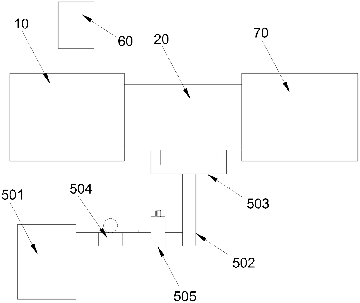
[0047] Such as Figures 1 to 19 As shown, a low-emissivity coated energy-saving glass production system includes a glass liquid mixing device 60, a glass forming processing table 10, a transition roller table 20 for conveying after forming, a flattening device 30 for controlling the surface during forming, and a glass forming table before forming. The slag removal device 40 of the processing table 10, the gas delivery device 50 for conveying the protective gas during the transmission process, and the finished product cutting device 70, the mixing device 60 is fixedly installed above the processing table 10, and the top surface of the processing table 10 There is a rectangular tin bath 11 in the center, the discharge end of the processing table 10 is horizontally and fixedly connected with the feed end of the transition roller table 20, and the flattening device 30 is arranged on the top surface of the processing table 10 and connected Slidingly connected, the slag removal devi...


PUM


Abstract

The invention discloses a production system for low-radiation coated energy-saving glass. The production system comprises a batch mixing device, a processing table, a transition roller table, a spreading device, a slag removing device, a gas conveying device and a finished product cutting device, wherein the batch mixing device is fixedly mounted above the processing table; the center of the top surface of the processing table is provided with a rectangular tin bath; the discharging end of the processing table is horizontally and fixedly connected with the feeding end of the transition rollertable; the spreading device is arranged on the top surface of the processing table and is slidably connected with the processing table; the slag removing device is also arranged on the top surface ofthe processing table and is slidably connected with the processing table; the gas conveying device is in communication with the transition roller table; and the feeding end of the finished product cutting device is fixedly connected with the discharging end of the gas conveying device. The apparatus of the invention improves the quality of the glass by means of uniform batch mixing, flat spreadingof materials, removal of impurities and control of the flow of shielding gas.

Description

technical field [0001] The invention relates to the technical field of glass processing and molding, in particular to a low-radiation coating energy-saving glass production system. Background technique [0002] Low-emissivity coated energy-saving glass has a high degree of application and strong performance, and belongs to a variety of glass. Glass is widely used, divided into colored glass, float silver mirror, float glass / automobile windshield grade, glass / various deep processing grade, glass / scanner grade, glass / coating grade, glass / mirror grade, mainly used in High-grade buildings, high-grade glass processing and solar photovoltaic curtain wall fields, as well as high-grade glass furniture, decorative glass, imitation crystal products, lamp glass, precision electronics industry, special buildings, etc. [0003] The production system of low-emissivity coated energy-saving glass includes mixing, feeding and forming, conveying, and cutting. The mixing needs to mix the molt...

Claims


Application Information

Patent Timeline
Patent Type & Authority Applications(China)
IPC IPC(8): C03B1/00C03B18/02C03B35/16C03B18/18
CPCC03B1/00C03B18/02C03B18/18C03B35/16
Inventor 林嘉宏
Owner TG ANHUI GLASS
Why Eureka
Eureka Blog
Learn More