
Box shaft hole inner wall grinding device used for speed changing box machining

A gearbox and box body technology, which is applied in the field of grinding devices for the inner wall of the box shaft hole, can solve the problems of affecting processing efficiency, poor practicability, and increasing labor intensity of workers, so as to achieve increased grinding effect, strong practicability, and novel design Effect

Inactive Publication Date: 2018-12-18
盐城市金发机械厂
View PDF8 Cites 23 Cited by
  • Summary
  • Abstract
  • Description
  • Claims
  • Application Information

AI Technical Summary

Problems solved by technology

[0004] The gearbox generally consists of a box and a transmission part and an operating part arranged inside the box. The structure and quality of the gearbox box directly affect the assembly quality and work efficiency of the entire system. Most of the box of the gearbox is integrally formed by injection molding. Afterwards, the shaft holes of various gear connection shafts are processed on the outer wall of the box. After the shaft holes are processed, we need to grind the inner wall of the shaft holes to eliminate the burrs generated during the drilling process to ensure the shaft The matching accuracy between the box and the existing shaft hole inner wall grinding method is to manually hold the grinding head and move along the shaft hole inner wall circumference. This operation method not only increases the labor intensity of the workers, but also affects Processing efficiency, practicality is not strong

Method used


Image

  • Box shaft hole inner wall grinding device used for speed changing box machining
  • Box shaft hole inner wall grinding device used for speed changing box machining
  • Box shaft hole inner wall grinding device used for speed changing box machining

Examples


Embodiment Construction

[0022] It should be noted that, in the case of no conflict, the embodiments of the present invention and the features in the embodiments can be combined with each other.

[0023] In describing the present invention, it should be understood that the terms "center", "longitudinal", "transverse", "upper", "lower", "front", "rear", "left", "right", " The orientations or positional relationships indicated by "vertical", "horizontal", "top", "bottom", "inner" and "outer" are based on the orientations or positional relationships shown in the drawings, and are only for the convenience of describing the present invention and Simplified descriptions, rather than indicating or implying that the device or element referred to must have a particular orientation, be constructed and operate in a particular orientation, and thus should not be construed as limiting the invention. In addition, the terms "first", "second", etc. are used for descriptive purposes only, and should not be understood ...


PUM


Abstract

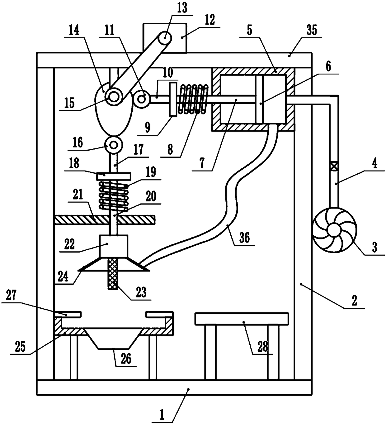
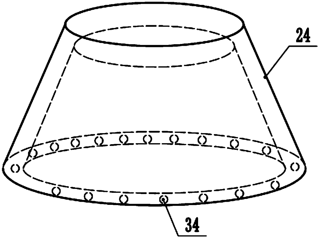
The invention discloses a box shaft hole inner wall grinding device used for speed changing box machining. The device comprises a base. Supporting frames are mounted on the two sides of the upper endof the base correspondingly. A top plate is mounted at the upper ends of the supporting frames. A driving motor is mounted in the middle of the upper end of the top plate. A driving belt pulley is mounted in the middle of the front end of the driving motor and connected with a driven belt pulley through a belt. The rear end of the driven belt pulley is connected with a rotary cam coaxially. The right end of the rotary cam makes contact with a first guide ball. The right end of the first guide ball is connected with a first limit rod. The right end of the first limit rod is connected with a first limit plate. The right end of the first limit plate is connected with a piston rod. The lower end of the rotary cam makes contact with a second guide ball. The lower end of the second guide ball isconnected with a second limit rod. The lower end of the second limit rod is connected with a second limit plate. The lower end of the second limit plate is connected with a lifting rod. According tothe box shaft hole inner wall grinding device, a grinding head can move up and down along the inner wall of a shaft hole during grinding, and in addition, a gas injection cavity can spray out gas which can be used for blowing away disintegrating slag produced during grinding in time.

Description

technical field [0001] The invention relates to the technical field of gearbox processing equipment, in particular to a grinding device for the inner wall of a shaft hole of a gearbox used for processing a gearbox. Background technique [0002] The gearbox mainly refers to the gearbox of the car, which is divided into manual and automatic. The manual gearbox is mainly composed of gears and shafts, and the variable speed and torque are generated through different gear combinations; It is composed of torque converter, planetary gear, hydraulic pitch change system and hydraulic control system. Variable speed and torque are achieved through hydraulic transmission and gear combination. [0003] The gearbox is a very important part of the vehicle. It can change the transmission ratio and expand the torque and speed of the driving wheels. With the development of modern technology, the gearbox has also been upgraded. From the initial manual gearbox to the current stepless gearbox,...

Claims


Application Information

Patent Timeline
Patent Type & Authority Applications(China)
IPC IPC(8): B24B5/48B24B55/06
CPCB24B5/48B24B55/06
Inventor 周星辰
Owner 盐城市金发机械厂
Learn More