
Haptic feedback device

A tactile feedback, initial position technology, applied in the direction of instrument, electrical digital data processing, user/computer interaction input/output, etc., can solve the problems of complex production process, slow response speed, large energy loss, etc., to achieve the transmission effect Good results

Pending Publication Date: 2018-12-14
HUAQIAO UNIVERSITY
View PDF4 Cites 1 Cited by
  • Summary
  • Abstract
  • Description
  • Claims
  • Application Information

AI Technical Summary

Problems solved by technology

[0003] Traditional tactile feedback devices generally use vibration motors based on electromagnetic induction effects. Their complex structures lead to complex production processes and slow response speeds, making it difficult for products to have an excellent user experience.
[0004] Or, for example, the Chinese patent authorization announcement number is CN203084648U, and the patent name is a utility model patent for a tactile feedback vibrator. The variable amplitude block, the variable amplitude block is transmitted to the vibrating substrate, and finally the mass block is driven to reciprocate synchronously through the body of the vibrating substrate, the transmission distance of mechanical energy is relatively long, and the energy loss is large, so that the vibration effect felt by the human body is not obvious

Method used


Image

  • Haptic feedback device
  • Haptic feedback device

Examples


Embodiment Construction

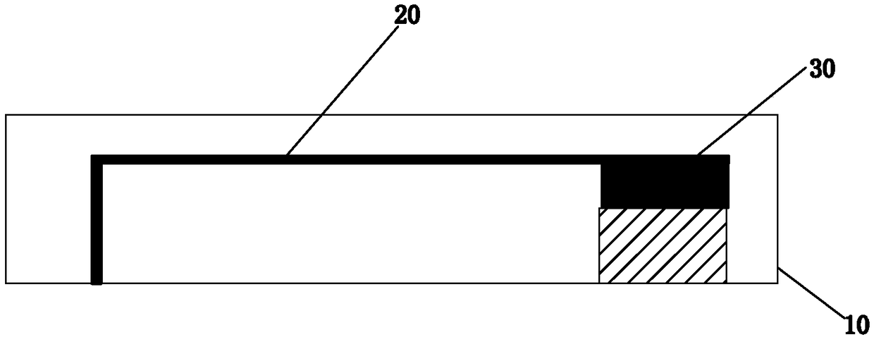
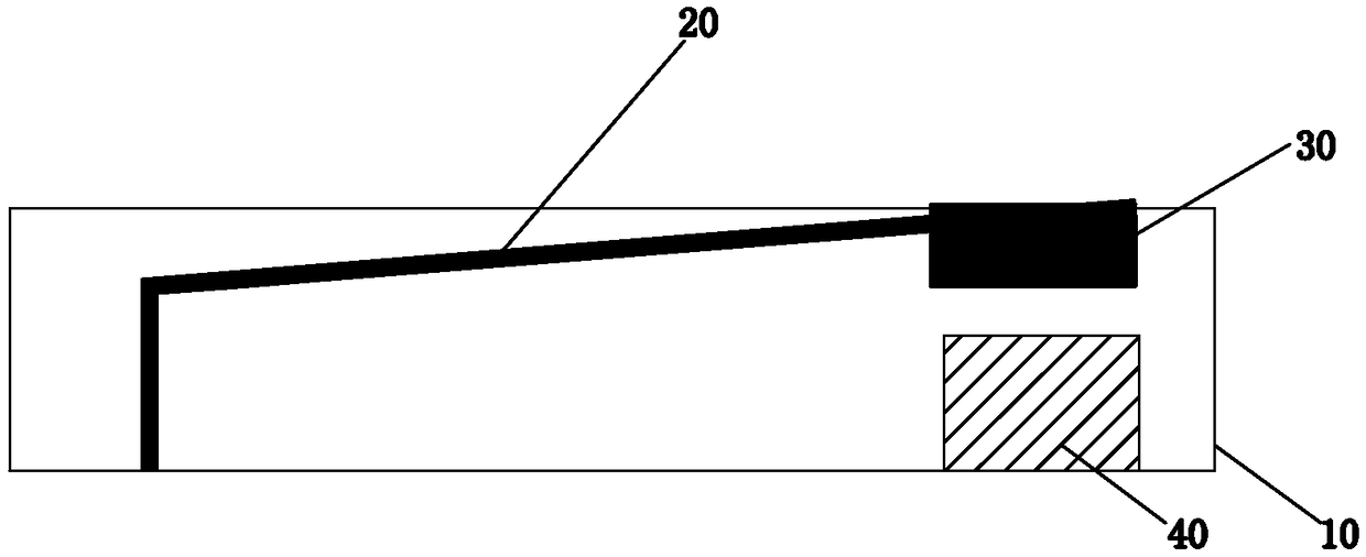
[0019] Please check Figure 1 to Figure 2 , a preferred embodiment of the tactile feedback device, the tactile feedback device includes a housing 10 , an elastic substrate 20 , a mass 30 and a laminated piezoelectric ceramic 40 .

[0020] The casing 10 has a rectangular shape.

[0021] The laminated piezoelectric ceramics 40 are fixed on the inner bottom surface of the casing 10 . In this embodiment, the laminated piezoelectric ceramic 40 is in the shape of a square.

[0022] In this embodiment, the laminated piezoelectric ceramic 40 is fixed to the inner bottom surface of the housing 10 by glue bonding or fitting or pressing.

[0023] The mass block 30 is affixed to one end of the elastic substrate 20 and moves between the initial position and the impact position, the other end of the elastic substrate 20 is affixed in the housing 10, and the mass block 30 abuts against the stacked On the top surface of the piezoelectric ceramic 40, the laminated piezoelectric ceramic 40 c...


PUM


Abstract

A haptic feedback device includes: a shell, an elastic substrate, a mass block and laminated piezoelectric ceramic, the laminate piezoelectric ceramic is fixedly connected to the bottom surface of theshell, the mass block is secured to one end of the elastic substrate and move between an initial position and an impact position, and the other end of the elastic substrate is fixedly connected in the shell. At the initial position, the mass block abuts against the top surface of the laminate piezoelectric ceramic; after receiving the driving signal, the laminated piezoelectric ceramic can be longitudinally telescoped to drive the mass to move from the initial position to the impact position. When the mass block moves to the impact position, the mass block drives the elastic substrate to impact the shell, and the mass block moves from the impact position to the initial position under the elastic action of the elastic substrate to impact the laminated piezoelectric ceramic. The mechanicalenergy transmission path of the haptic feedback device is short, and the energy loss is small, so that the vibration amplitude is large, the response is quick, and the human can feel the strong vibration effect from the shell.

Description

technical field [0001] The present invention relates to tactile feedback devices. Background technique [0002] At present, in our daily life, in order to increase the user experience of products, many product manufacturers have added tactile feedback devices that provide tactile confirmation to their products, such as mobile phone vibration reminders for incoming calls, electronic touch screens and other functions, which have improved the use of products. Operability and simplicity in the process for easy user identification. [0003] Traditional tactile feedback devices generally use vibration motors based on electromagnetic induction effects. Their complex structures lead to complex production processes and slow response speeds, making it difficult for products to provide excellent user experience. [0004] Or, for example, the Chinese patent authorization announcement number is CN203084648U, and the patent name is a utility model patent for a tactile feedback vibrator. ...

Claims


Application Information

Patent Timeline
IPC IPC(8): G06F3/01
CPCG06F3/016
Inventor 王寅曹俊廖梦娇余卿范伟
Owner HUAQIAO UNIVERSITY
Learn More