Eureka AIR delivers breakthrough ideas for toughest innovation challenges, trusted by R&D personnel around the world.

Coal gasification process and device for liquid slagging and high-temperature coke loopback

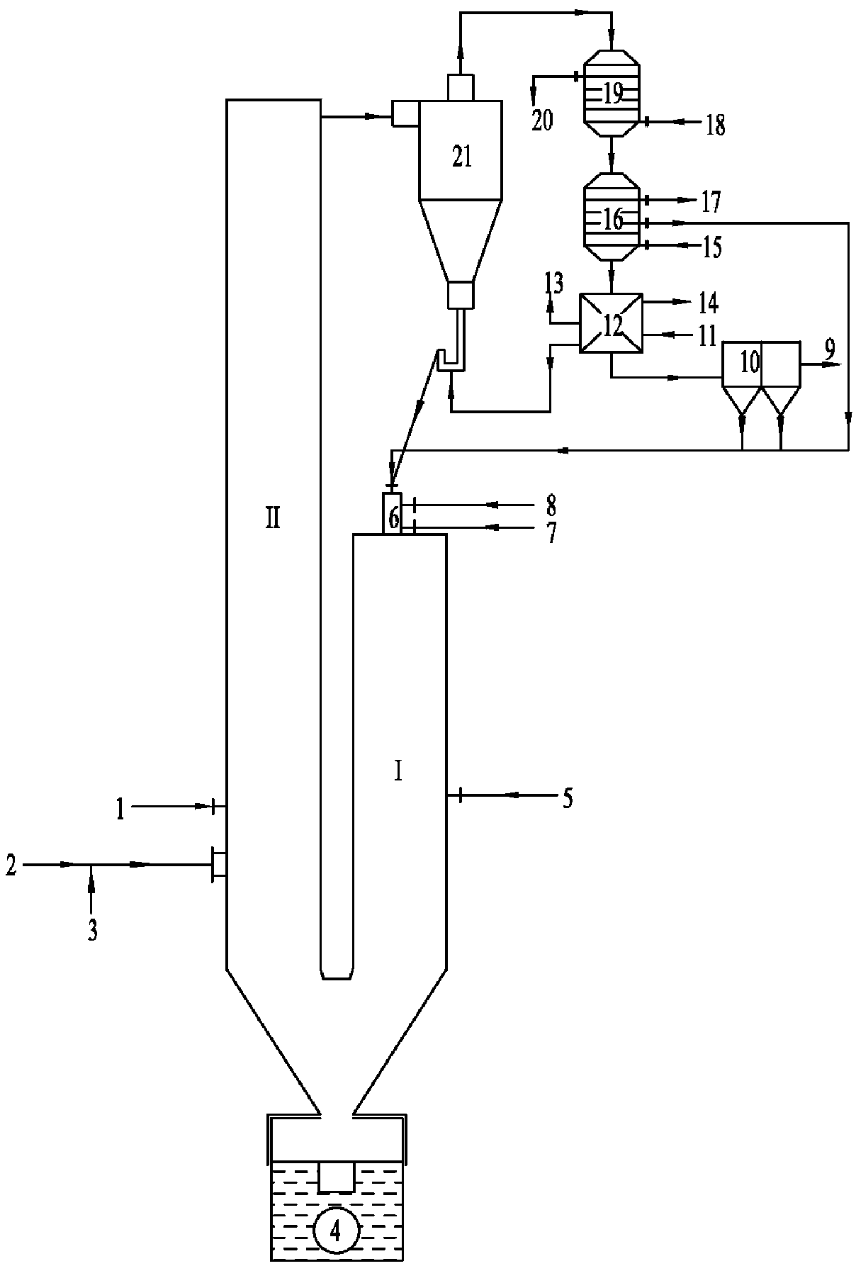
A technology for liquid slag discharge and coal gasification, applied in the field of coal gasification, can solve the problems of reducing the calorific value of pyrolysis gas, affecting the carbon conversion rate, and high carbon content in the bottom slag, so as to improve the carbon conversion rate, reduce the content of ineffective gas, The effect of reducing carbon content

Active Publication Date: 2018-12-14
SHANDONG UNIV
View PDF7 Cites 1 Cited by
  • Summary
  • Abstract
  • Description
  • Claims
  • Application Information

AI Technical Summary

Problems solved by technology

The applicant proposed in the application number 201711041111.7 "a pulverized coal gasification device and process for producing high-calorific-value gas with low residual carbon content" that a U-shaped two-stage gas generator can greatly increase the coal gasification rate while producing high-calorific-value gas. utilization rate, but there are still the following problems: (1) the solid-state slag discharge method is adopted, and the bottom slag contains high carbon content, which affects the overall carbon conversion rate; (2) some oxygen is introduced into the low-temperature section, which reduces the heat of the pyrolysis gas to a certain extent. (3) The efficiency of the separator is that a large amount of semi-coke is still brought out at the outlet, which affects the carbon conversion rate and reduces the gasification efficiency

Method used


Image

  • Coal gasification process and device for liquid slagging and high-temperature coke loopback
  • Coal gasification process and device for liquid slagging and high-temperature coke loopback
  • Coal gasification process and device for liquid slagging and high-temperature coke loopback

Examples


Embodiment Construction

[0015] It should be pointed out that the following detailed description is exemplary and is intended to provide further explanation to the present application. Unless defined otherwise, all technical and scientific terms used herein have the same meaning as commonly understood by one of ordinary skill in the art to which this application belongs.

[0016] It should be noted that the terminology used here is only for describing specific implementations, and is not intended to limit the exemplary implementations according to the present application. As used herein, unless the context clearly dictates otherwise, the singular is intended to include the plural, and it should also be understood that when the terms "comprising" and / or "comprising" are used in this specification, they mean There are features, steps, operations, means, components and / or combinations thereof.

[0017] The high temperature of the high-temperature coke in this application refers to a temperature of 900-1...


PUM


Abstract

The invention discloses a coal gasification process and device for liquid slagging and high-temperature coke loopback. The device comprises a U-shaped gas generator and a high-temperature separator, wherein the U-shaped gas generator comprises a high-temperature section and a low-temperature section which are of a U shape; the high-temperature section and the low-temperature section share a ash bucket; an outlet of the U-shaped gas generator is formed in the top of the low-temperature section and connected with an inlet of the high-temperature separator; a coal powder inlet, an air inlet and afirst vapor inlet are formed in the top of the high-temperature section; the coal powder inlet is connected with each of a coal powder source and a high-temperature coke outlet of the high-temperature separator; a second vapor inlet is formed in the middle part of the high-temperature section; a coal powder feeding port and a third vapor inlet are formed in the bottom of the low-temperature section; the third vapor inlet is located above the coal powder feeding port; the coal powder feeding port is connected with a coal powder pipeline; and the coal powder pipeline is provided with a gas pipeline. Through the adoption of the device, a carbon conversion rate can be provided and the efficient utilization of coal can be realized.

Description

technical field [0001] The invention belongs to the technical field of coal gasification, and in particular relates to a coal gasification process and device for liquid slag discharge and high-temperature coke return. Background technique [0002] my country's energy structure determines the status of coal as the main energy source, because coal combustion will produce SO 2 , NO x , dioxins, heavy metals, dust and other pollutants, with the increasingly prominent environmental problems, the efficient and clean utilization of coal has become a hot spot of social concern, and coal gasification, as the core technology to realize the efficient and clean utilization of coal, has developed rapidly in recent years. The applicant proposed in the application number 201711041111.7 "a pulverized coal gasification device and process for producing high-calorific-value gas with low residual carbon content" that a U-shaped two-stage gas generator can greatly increase the coal gasification...

Claims


Application Information

Patent Timeline
IPC IPC(8): C10J3/48C10J3/46C10J3/72C10J3/84C10J3/86
CPCC10J3/46C10J3/48C10J3/721C10J3/84C10J3/86C10J2300/093C10J2300/0956C10J2300/0976C10J2300/1603
Inventor 马春元王涛张振周滨选付加鹏
Owner SHANDONG UNIV
Why Eureka
Eureka Blog
Learn More