Eureka AIR delivers breakthrough ideas for toughest innovation challenges, trusted by R&D personnel around the world.

Multi-rotor plant-protection unmanned aerial vehicle with ultra-wide spraying width

A plant protection drone and multi-rotor technology, applied in the direction of rotorcraft, motor vehicles, aircraft parts, etc., can solve the problems of uncontrollable, non-uniform deterioration, non-constant impact, etc., to ensure permeability, improve stability, Improve the effect of spraying effect

Inactive Publication Date: 2018-12-14
北京国信聚惠科技有限公司
View PDF7 Cites 5 Cited by
  • Summary
  • Abstract
  • Description
  • Claims
  • Application Information

AI Technical Summary

Problems solved by technology

However, the spraying rate of the liquid medicine remains basically unchanged, which leads to the non-constant and uncontrollable influence of the wind field of the downwash airflow on the spraying flow field of the liquid medicine.
Increasing the spray width of the plant protection UAV can make the UAV spray the same weight of liquid medicine in less time, thereby reducing the time of the UAV, reducing power consumption, and improving the efficiency of plant protection operations. However, the current center The non-uniformity of the downwash wind field generated by the symmetrical multi-rotor UAV in the direction of the spray length will be further deteriorated

Method used


Image

  • Multi-rotor plant-protection unmanned aerial vehicle with ultra-wide spraying width
  • Multi-rotor plant-protection unmanned aerial vehicle with ultra-wide spraying width

Examples


Embodiment Construction

[0028] The purpose of the present invention is to provide a multi-rotor plant protection UAV with an ultra-wide spray width. The multi-rotor plant protection UAV with an ultra-wide spray width can realize the spraying of pesticides with an ultra-wide spray width to improve operation efficiency, and at the same time can produce Uniform, constant and controllable downwash airflow field to improve liquid penetration performance.

[0029] In order to enable those skilled in the art to better understand the technical solutions of the present invention, the present invention will be further described in detail below in conjunction with the accompanying drawings and specific embodiments.

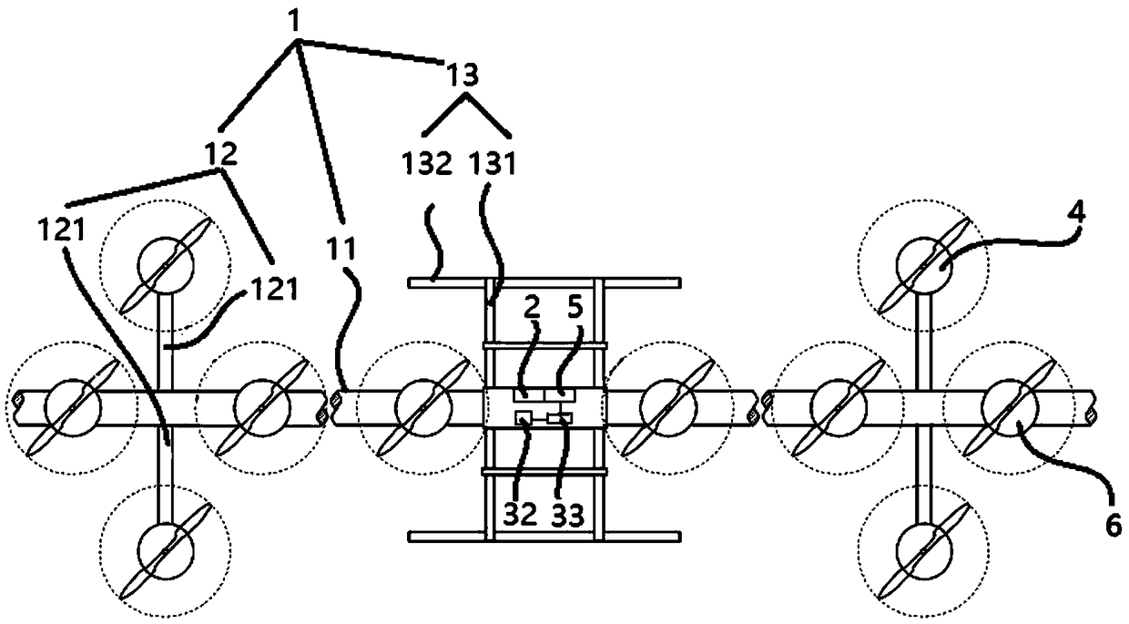
[0030] Such as figure 1 and figure 2 as shown, figure 1 It is a schematic diagram of the top view structure of a specific embodiment of the ultra-wide spray width multi-rotor plant protection drone provided by the present invention, figure 2 for figure 1 Schematic diagram of the main view str...


PUM


Abstract

The invention discloses a multi-rotor plant-protection unmanned aerial vehicle with an ultra-wide spraying width, and relates to the fields of multi-rotor unmanned aerial vehicle systems and unmannedaerial vehicle agricultural plant protection technologies. The multi-rotor plant-protection unmanned aerial vehicle comprises a frame, a flight control system used for controlling flying of the unmanned aerial vehicle, a liquid pesticide spraying system used for spraying a liquid pesticide, and a plurality of first rotors which are arranged on the frame and used for controlling movement and postures of the unmanned aerial vehicle, and also comprises a power supply system used for supplying power for the unmanned aerial vehicle, and a landing chassis system used for supporting the unmanned aerial vehicle to be placed on the ground, wherein the frame comprises an ultra-long keel rod, and the liquid pesticide spraying system comprises a plurality of spray heads which are arranged at the lowerpart of the ultra-long keel rod in a straight-line shape along the length direction of the ultra-long keel rod to realize spraying of the liquid pesticide with ultra-wide spraying width and improve spraying efficiency; moreover, the multi-rotor plant-protection unmanned aerial vehicle also comprises a plurality of second rotors which are arranged at the upper part of the ultra-long keel rod and can generate constant elevating force, wherein the plurality of rotating second rotors can generate a downwash airflow wind field matching with the flow field of the liquid sprayed from the plurality of spray heads to improve spraying uniformity and permeability of the liquid pesticide and enhance spraying effects.

Description

technical field [0001] The invention relates to the field of multi-rotor unmanned aerial vehicle system and unmanned aerial vehicle agricultural plant protection technology, in particular to an ultra-wide spray width multi-rotor plant protection unmanned aerial vehicle. Background technique [0002] Multi-rotor UAVs have been widely used in the field of agricultural plant protection. When working, the downwash wind field generated by the UAV's multiple rotors can increase the permeability of the sprayed liquid, improve the spraying effect, and reduce the consumption of pesticides. [0003] However, the existing multi-rotor plant protection drones also have some shortcomings, mainly in that the influence of the downwash air field on the liquid spraying flow field is non-uniform, non-constant, and uncontrollable. First of all, the rotor layout of multi-rotor plant protection drones is generally centrosymmetric, with multiple arms surrounding the central frame. The multiple no...

Claims


Application Information

Patent Timeline
Patent Type & Authority Applications(China)
IPC IPC(8): A01M7/00B64C27/08B64C27/32B64D1/18
CPCA01M7/0042B64C27/08B64C27/32B64D1/18
Inventor 刘晓阳林海英王滨
Owner 北京国信聚惠科技有限公司
Why Eureka
Eureka Blog
Learn More