
A method for improving ltcc co-firing mismatch

A technology of co-firing and sintering temperature, which is applied in the manufacture of electrical components, circuits, semiconductors/solid-state devices, etc. It can solve problems such as deterioration of standing wave ratio, increase of filter insertion loss, and different temperatures, and achieve co-firing loss. Improvement of matching ratio, reduction of mismatching ratio, and improvement of reliability

Active Publication Date: 2020-11-24
広东风华特种新材料股フン有限公司
View PDF6 Cites 0 Cited by
  • Summary
  • Abstract
  • Description
  • Claims
  • Application Information

AI Technical Summary

Problems solved by technology

When LTCC is co-fired, the mismatch between the sintering characteristics of the ceramic body and the conductive paste is mainly reflected in the difference in the temperature at which the sintering densification is completed; the sintering shrinkage of the substrate and the paste is inconsistent; the speed of the sintering densification does not match, etc.
These mismatches can easily lead to unevenness, warping, delamination of the substrate surface after firing, and decreased adhesion of metal wiring, etc.
In practice, the ceramic body and the conductive paste with the same maximum shrinkage can be used, but the sintering and densification speeds of the two often do not match, and the shrinkage rate has a certain difference. The conductive layers are not well bonded together, and there are large gaps between them
For some high-frequency functional devices or functional substrates, there is a gap between the metal layer and the ceramic body, which is equivalent to changing the structure of the entire product, which will greatly affect its electrical performance, such as the increase in the insertion loss of the filter, and the Burpee Variation, etc.
[0004] In view of this, it is an urgent need to provide a method for improving the LTCC co-firing mismatch, and to solve the problem of the temperature point and shrinkage rate mismatch between the LTCC ceramic body and the inner layer conductive paste during the sintering process.

Method used


Image

  • A method for improving ltcc co-firing mismatch
  • A method for improving ltcc co-firing mismatch
  • A method for improving ltcc co-firing mismatch

Examples


Embodiment Construction

[0019] The specific implementation manners of the present invention will be further described in detail below in conjunction with the accompanying drawings and embodiments. The following examples are used to illustrate the present invention, but are not intended to limit the scope of the present invention.

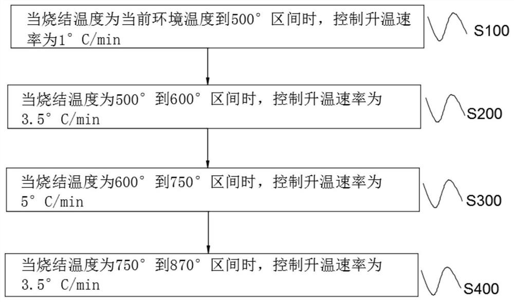
[0020] The invention provides a method for improving LTCC co-firing mismatch. The method comprises that during the co-firing process of the LTCC ceramic body and the inner layer conductive paste, when the sintering temperature reaches the rapid shrinkage temperature range of the inner layer conductive paste , the heating rate is increased, and when the sintering temperature exceeds the rapid shrinkage temperature range of the conductive paste, the normal heating rate is resumed.

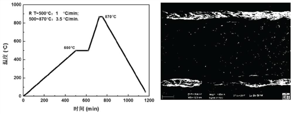
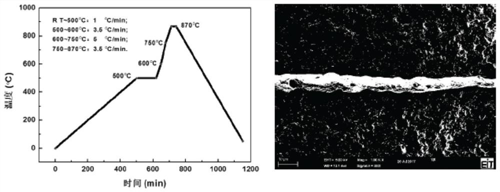
[0021] refer to figure 1 and Figure 6 , is an embodiment of the method for improving the LTCC co-firing mismatch of the present invention, and the method for improving the LTCC co-firing misma...


PUM

PropertyMeasurementUnit
glass transition temperatureaaaaaaaaaa
shrinkageaaaaaaaaaa

Abstract

The invention provides a method for improving LTCC co-firing mismatch. The method comprises the following steps: in the co-firing process of the LTCC ceramic body and the inner layer conductive paste,when the sintering temperature reaches the fast shrinkage temperature range of the inner layer conductive paste, the heating rate is increased, and when the sintering temperature exceeds the fast shrinkage temperature range of the conductive paste, the normal heating rate is restored. The method for improving the LTCC co-firing mismatch improves the shrinkage matching between a conductive metal layer and a substrate to a large extent without affecting the sintering density of the product, widens the range of material selection, greatly improves the reliability of the LTCC substrate and the functional device, and realizes more excellent electric performance.

Description

technical field [0001] The invention relates to the technical field of ceramic material preparation methods, in particular to a method for improving LTCC co-firing mismatch. Background technique [0002] LTCC technology is one of the mainstream integrated packaging technologies at present. It has many advantages. The electronic components prepared by LTCC technology have the advantages of high reliability, high performance and high frequency. An important means of development in the direction of globalization, etc., has been more and more widely used. [0003] But at the same time, LTCC also has difficulties related to reliability. For example, the shrinkage rate of LTCC ceramic body and inner layer conductive paste is one of the important challenges, which is related to the quality of multilayer metallization wiring. When LTCC is co-fired, the mismatch between the sintering characteristics of the ceramic body and the conductive paste is mainly reflected in the difference i...

Claims


Application Information

Patent Timeline
Patent Type & Authority Patents(China)
IPC IPC(8): H01L21/48
CPCH01L21/4857
Inventor 叶文生黄昆陈涛黄明富张志龙苏健雄戴燕城
Owner 広东风华特种新材料股フン有限公司
Learn More