
Photon shutter device

A light gate and photon technology, applied in optics, optical components, instruments, etc., can solve problems such as ultra-high vacuum environment damage, equipment damage, and high light source power, so as to avoid material failure, occupy less space, and increase the light-receiving surface Effect

Pending Publication Date: 2018-12-11
SHANGHAI INST OF APPLIED PHYSICS - CHINESE ACAD OF SCI
View PDF5 Cites 3 Cited by
  • Summary
  • Abstract
  • Description
  • Claims
  • Application Information

AI Technical Summary

Problems solved by technology

[0007] However, the existing photonic shutters suitable for the front end of the Canted beamline can only control the two beamlines that have been completely separated in the front end, and the structure of the existing photonic shutters is not suitable for the Canted front end with an ultra-small angle. Area
[0008] For the Canted front-end area with an ultra-small included angle, after the two beamlines mixed together are split by the splitter diaphragm device, the two beamlines cannot be completely separated due to the small angle between the two beamlines, and the two beamlines at the position of the beamline The two beams still share a set of devices, so the two beamlines cannot be completely separated in the front-end area, and the existing photonic shutter has only one light-passing light-blocking hole, which can control one beam in the Canted front-end area with an ultra-small angle. At the same time, the other beam will be blocked by the photon shutter, and cannot reach the downstream beamline and experimental station smoothly; in addition, because the Canted beamline is an insert light source, the power of the light source is very large, and the beam directly hits the beamline It is very dangerous to pass through the end face of the light equipment or the tube wall. It may cause damage to the equipment due to excessive power and cause vacuum leakage.
Since the operation of the light source has an ultra-high vacuum requirement for the entire front-end area, once there is a vacuum leak, a control chain reaction will be initiated to protect the storage ring by kicking the beam. Once the storage ring kicks the beam, it will affect the normal operation of other beamline stations
At the same time, because the front-end area is in a radiation environment, if a vacuum leak occurs, not only the ultra-high vacuum environment will be destroyed, but also the safety of equipment and people downstream of the front-end area will be threatened.

Method used


Image

  • Photon shutter device
  • Photon shutter device
  • Photon shutter device

Examples


Embodiment Construction

[0030] In order to enable those skilled in the art to better understand the solution of the present invention, the present invention will be further described in detail below in conjunction with the accompanying drawings and specific embodiments. The specific embodiments described here are only used to explain the present invention, not to limit the present invention.

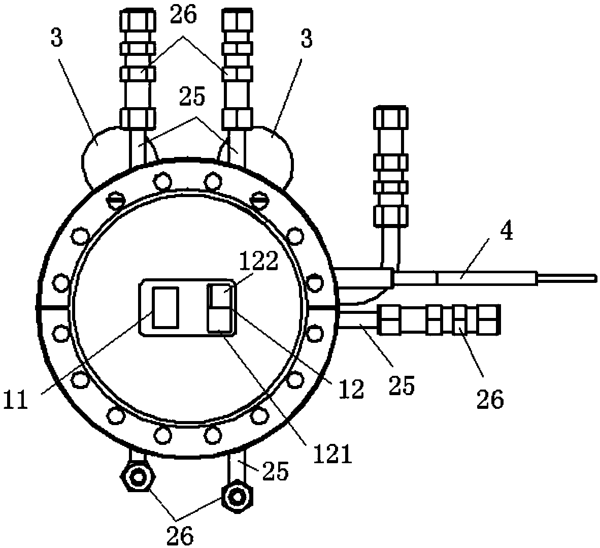
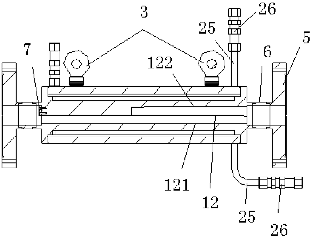
[0031] Such as figure 1 Shown is a photonic shutter device according to an embodiment of the present invention, which includes an absorption body 1 , a water cooling circulation system 2 , a collimation device 3 , a temperature detection device 4 , a connecting flange 5 and an adapter 6 .

[0032] The shape of the absorbing body 1 is a square structure, and several outer surfaces are set as reference planes, so as to facilitate welding and other processing of the collimation device 3, and also facilitate installation and debugging. In addition, the absorption body 1 is made of dispersion-strengthened copper-al...


PUM


Abstract

The invention provides a photon shutter device, and the device comprises an absorption main body, wherein the interior of the absorption main body is provided with a light hole and a composite hole, which are used for the passing of two light beams of the composite light beams entering the absorption main body; a water cooling circulation system; a plurality of collimating devices; at least one temperature detection device. The light hole is a rectangular through hole. The composite hole is provided with a light passing part located at the lower part, and a light blocking part located at the upper part. The light passing part is a left-right through channel, and the light blocking part is a wedge-shaped channel, wherein the width of the wedge-shaped channel gradually decreases in the traveling direction of a light beam. The tail end of the light blocking part is provided with an absorption light blocking plate. The setting of the light hole and the composite hole enables the device toachieve a purpose that the application of one light beam is not affected while the device achieves the light passing and blocking control of the other light beam in the composite light beams with a super-small inclined angle.

Description

technical field [0001] The invention relates to the field of synchrotron radiation light sources, and more particularly to a photonic shutter device. Background technique [0002] Synchrotron radiation is an electromagnetic wave emitted along the tangential direction of the electron trajectory due to the change of state (speed and direction) when free electrons move in a magnetic field. Due to the characteristics of continuous spectrum, high brightness, and good collimation, it is widely used in physics, chemistry , life science, information science, energy and environmental science and many other scientific research and high-tech fields have a wide range of applications. The front end region is an important part of the synchrotron radiation beamline, which is both self-contained and associated with multiple systems. The main functions are to limit the size of the synchrotron radiation light, detect the position of the beam, absorb the heat load, realize the safety protecti...

Claims


Application Information

Patent Timeline
Patent Type & Authority Applications(China)
IPC IPC(8): G02B5/00
CPCG02B5/00
Inventor 贾丹丹祝万钱李勇军张敏薛松吴帅
Owner SHANGHAI INST OF APPLIED PHYSICS - CHINESE ACAD OF SCI
Learn More