Tunnel supporting pipe

A technology for pipe fittings and tunnels, applied in the field of support components for tunnel excavation, which can solve the problems of small concrete flow space and insufficient bonding strength, and achieve the effect of firm concrete structure strength

Active Publication Date: 2018-12-11
深圳市第一建筑工程有限公司
View PDF7 Cites 3 Cited by
  • Summary
  • Abstract
  • Description
  • Claims
  • Application Information

AI Technical Summary

Problems solved by technology

[0003] Now retrieve a patent document about a small catheter, its announcement number is CN 202165095 U, and its patent name is a tunnel grouting and grouting stop device. After the geological layer, since the outer wall of the small conduit is attached to the soil, there is less space for the concrete to flow between the two, and the bonding strength between the small conduit and the geological layer is insufficient

Method used


Image

  • Tunnel supporting pipe
  • Tunnel supporting pipe
  • Tunnel supporting pipe

Examples


Embodiment 1

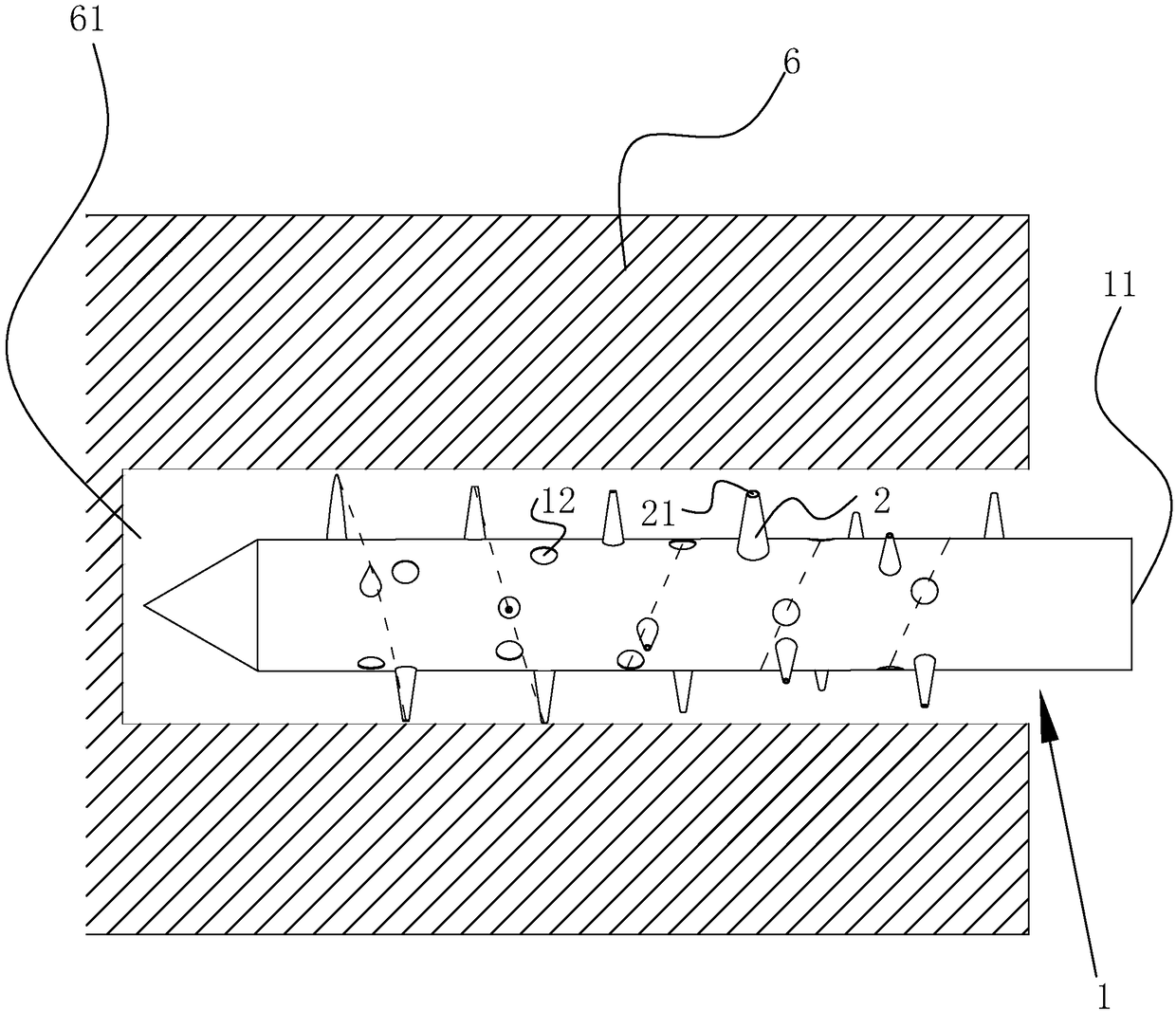
[0042] Example 1, pipe fittings used for tunnel support, such as figure 1 As shown, the tube body 1 is included. The body of the tube body 1 is a cylinder with a hollow inside; one end of the tube body 1 is conical, and the other end of the tube body 1 is provided with a grouting port 11.

[0043] A conical strut 2 is fixed on the outer wall of the pipe body 1, and the strut 2 is hollowed out to form a grouting hole 21; one end of the grouting hole 21 is connected to the hollow part of the pipe body 1, and the grouting hole 21 The other end of the grouting rod is placed at the outer end of the support rod 2; the minimum hole diameter of the grouting hole 21 is 2cm. When the slurry is poured into the grouting port 11 of this size, the mud will flow along the grouting hole 21 to The outer wall of the tube body 1. The support rod 2 is arranged along the spiral track of the length of the pipe body 1, figure 1 In the middle, the two dashed lines on the left refer to the spiral traject...

Embodiment 2

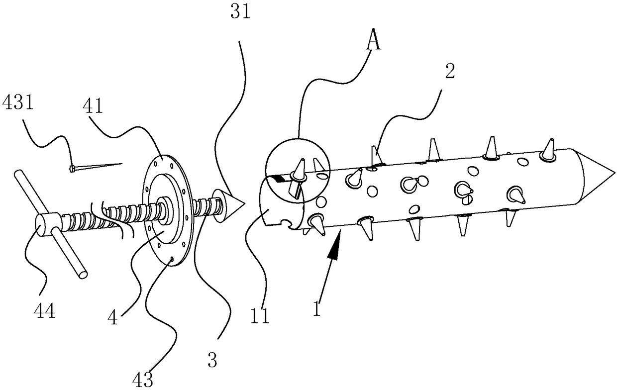
[0046] Embodiment 2, a pipe used for tunnel support, which is different from Embodiment 1 in that: figure 2 versus image 3 As shown, the outer wall of the tube body 1 is provided with an opening, and the support rod 2 can slide outward along the opening diameter of the tube body 1. The friction force between the support rod 2 and the wall of the opening is used to make the support rod 2 in It can be positioned on the opening without external force.

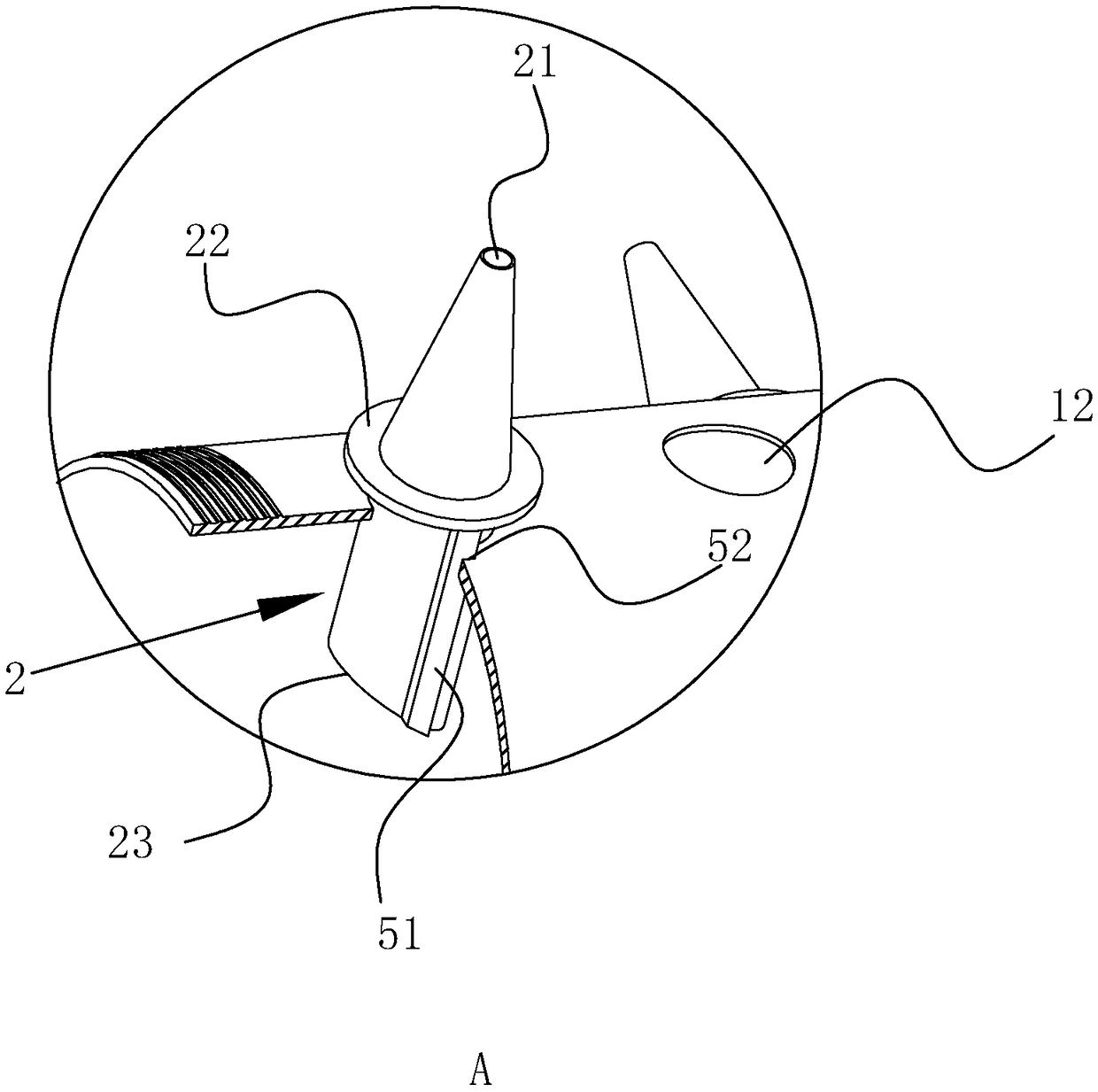
[0047] The support rod 2 is divided into two parts, one part is the cone part outside the tube body 1, and the other part is the cylindrical part inside the tube body 1. The bottom of the cone part is fixed with an annular stop 22, which is opposite to the tube The outer wall of the body 1 is blocked, making it difficult for the conical part of the strut 2 to retract into the tube body 1 as a whole.

[0048] The lower bottom surface of the cylindrical part of the support rod 2 is an elliptical inclined surface 23, and the inclined su...


PUM


Abstract

The invention discloses a tunnel supporting pipe. The technical scheme is characterized in that the tunnel supporting pipe comprises a hollow pipe body, one end of the pipe body is provided with a grouting port, protruding support rods are arranged on the outer wall of the pipe body, each support rod is provided with a first grouting hole communicated with the interior of the pipe body, the support rods are helically arranged along the length direction of the pipe body, and one end, facing a geological stratum, of each support rod is conical. The outer wall of the pipe body is provided with second grouting holes communicated with the interior of the pipe body, the first grouting holes and the second grouting holes are distributed in a double-helix form on the outer wall of the pipe body, and the support rods are slidably inserted into the pipe body. Retaining blocks which are abutted against the outer wall of the pipe body to limit retraction of the support rods are fixed to the support rods, and one end, extending into the pipe body, of each support rod is provided with a slope facing the grouting port. The end, extending into the pipe, of a push rod is provided with a conical face which takes the slopes as fitting faces to push the support rods to extend out. By the support rods protruding the outer wall of a small guide pipe, the small guide pipe can be supported at the center of a geological hole, and a sufficient paste flowing space is reserved between the outer wall of the small guide pipe and the wall of the geological hole.

Description

Technical field [0001] The invention relates to a support member for tunnel excavation, and more specifically, it relates to a pipe fitting for tunnel support. Background technique [0002] In the construction of the tunnel advance support project, the use of a small pipe advance support system can play a good role in preventing collapse and improving the stability of the surrounding rock. [0003] I have retrieved a patent document about small catheters, its announcement number is CN 202165095 U, and its patent name is a tunnel grouting grouting device. The scheme discloses that a grouting port is opened in the small catheter. When the small catheter is inserted After the geological layer, because the outer wall of the small pipe adheres to the soil, there is less space for concrete flow between the two, and the bonding strength between the small pipe and the geological layer is insufficient. Summary of the invention [0004] The purpose of the present invention is to provide a pi...

Claims


Application Information

Patent Timeline
Patent Type & Authority Applications(China)
IPC IPC(8): E21D11/10
CPCE21D11/10E21D11/107
Inventor 温巧生王旭峰何阳超余海明阳翔陈鹏
Owner 深圳市第一建筑工程有限公司
Why Eureka
Try Eureka