
Sputtering plating system for plastic and rubber pipe

A plastic tube and sputtering technology, which is applied in sputtering plating, ion implantation plating, vacuum evaporation plating, etc., can solve the problems of troublesome cleaning of sputtering device, limited uniformity of sputtering, and low efficiency, so as to improve efficiency , Improve cleaning efficiency and improve uniformity

Active Publication Date: 2018-12-11
莘县鲁开综合服务有限公司
View PDF2 Cites 4 Cited by
  • Summary
  • Abstract
  • Description
  • Claims
  • Application Information

AI Technical Summary

Problems solved by technology

[0004] In the above-mentioned Patent Document 1, the coating efficiency is improved by adding a plurality of first material rods and second material rods; The axis rotates in reverse at the same time, so that the coating of the workpiece to be plated is more uniform; but the cleaning of the sputtering device is troublesome and the efficiency is low. At the same time, because the sputtering device has an inner ring and an outer ring, it prevents multiple first materials The rod blocks multiple second material rods in the direction parallel to the top plate, so that the coating film of the workpiece to be plated is more uniform. It can only be as uniform as possible, but the uniformity of sputtering is limited.

Method used


Image

  • Sputtering plating system for plastic and rubber pipe
  • Sputtering plating system for plastic and rubber pipe

Examples


Embodiment Construction

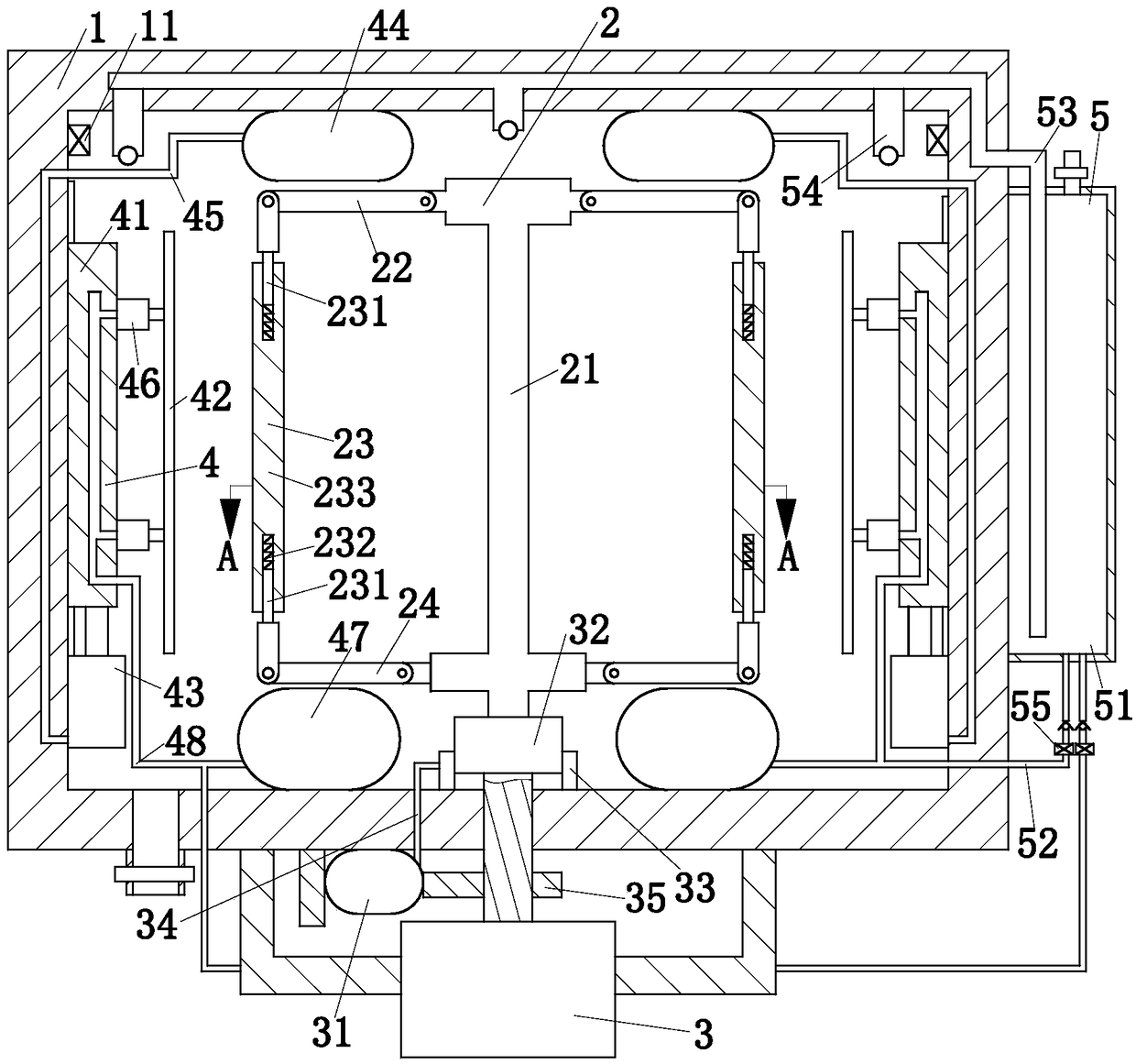
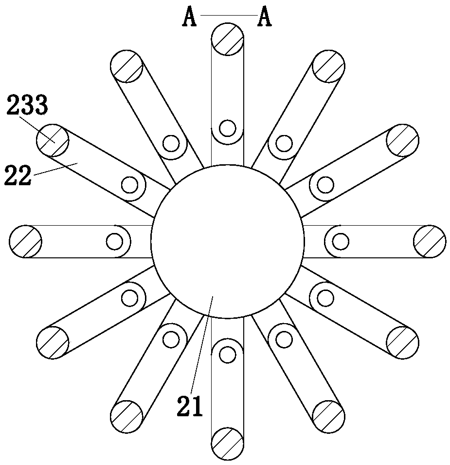
[0022] use Figure 1 to Figure 2 The plastic pipe sputtering system of the present invention will be described as follows.

[0023] Such as Figure 1 to Figure 2 As shown, a plastic pipe sputtering system according to the present invention includes a sputtering box 1, a workpiece holder 2, a motor 3, a target module 4, a heater 11, and an automatic cleaning module 5. The sputtering box 1 The bottom end is provided with a water outlet pipe and a water valve is provided on the outlet pipe; the motor 3 is fixed outside the sputtering box 1; the workpiece holder 2 is located in the center of the sputtering box 1, and the workpiece holder 2 is driven to rotate by the motor 3; The target module 4 is installed on the inner wall of the sputtering box 1. The target module 4 is adjacent to the workpiece holder 2, and the target module 4 can move up and down or laterally close to the workpiece holder 2. The main body of the automatic cleaning module 5 is fixed on the sputtering box. On th...


PUM


Abstract

The invention belongs to the technical field of film plating, in particular to a sputtering plating system for a plastic and rubber pipe. The sputtering plating system comprises a sputtering plating box, a workpiece frame, a motor, a target module, a heater and an automatic cleaning module, wherein the motor is fixedly arranged at the exterior of the sputtering plating box; the workpiece frame ispositioned at the center of the interior of the sputtering plating box, and is driven by the motor to rotate; the target module is arranged at the inner wall of the sputtering plating box, can be moved up and down, and be moved along the transverse direction to get close to the workpiece frame; the automatic cleaning module is used for cleaning the sputtering plating box before sputtering plating;the heater is positioned at the upper end of the inner wall of the sputtering plating box, and is used for drying the cleaned sputtering plating box. The sputtering plating system has the advantagesthat the automatic cleaning module is used for spraying water into the sputtering plating box to clean, so that the efficiency in the whole sputtering plating process of the plastic and rubber pipe isimproved; the motor is used for driving the workpiece frame to rotate, and the sputtering plating of the plastic and rubber pipe is uniform; the target module is moved up and down, or is moved alongthe transverse direction, so as to complete uniform sputtering plating of the plastic and rubber pipe, and improve the sputtering plating quality of the plastic and rubber pipe.

Description

Technical field [0001] The invention belongs to the technical field of film coating, and specifically is a plastic pipe sputtering system. Background technique [0002] Sputtering, usually refers to magnetron sputtering, is a high-speed low-temperature sputtering method. This process requires a vacuum degree of about 1×10⁻³ Torr, that is, a vacuum state of 1.3×10⁻³ Pa, inert gas argon (Ar) is filled, and the plastic substrate (anode) and the metal target (cathode) are added between When the high-voltage direct current is applied, the electrons generated by the glow discharge excite the inert gas to generate plasma. The plasma blasts out the atoms of the metal target and deposits on the plastic substrate. However, in the existing plastic pipe sputtering devices, most of the sputtered plastic pipes have defects, the sputtering is uneven, and the efficiency of the entire sputtering process is low. [0003] Patent Document 1: A sputtering device, application number 2010106052656 [00...

Claims


Application Information

Patent Timeline
Patent Type & Authority Applications(China)
IPC IPC(8): C23C14/35C23C14/50B08B9/093
CPCB08B9/093C23C14/35C23C14/505
Inventor 杨胜
Owner 莘县鲁开综合服务有限公司
Learn More