A battery swapping device for an electric vehicle

A technology for electric vehicles and vehicles, which is applied in the direction of electric vehicles, electric power devices, power devices, etc., and can solve the problems of no way to automatically replace the car's rechargeable battery and low efficiency

Active Publication Date: 2020-06-23
NORTH CHINA ELECTRIC POWER UNIV (BAODING) +1
View PDF1 Cites 0 Cited by
  • Summary
  • Abstract
  • Description
  • Claims
  • Application Information

AI Technical Summary

Problems solved by technology

[0002] For example, the patent No. is CN201510504102.1, an electric vehicle battery replacement device. Its technical characteristics are: it includes a car body, a lifting device and a battery replacement box. The battery replacement box is installed on the car body through a lifting device. A wheel is installed on the upper end of one side of the battery replacement box with a high-definition camera, and two mechanical arms and a battery tray are installed under the high-definition camera, and batteries, PLC control units, walking motors, etc. are installed in the car body and the battery replacement box. Elevator controller, smart chip, video acquisition module, remote control module, reducer and access battery motor, which can be easily moved to the battery rack or electric vehicle by controlling the car body, and the height of the mechanical arm can be adjusted through the lifting device. The replacement of the battery increases the accuracy of the battery replacement, improves the efficiency of the battery replacement, and reduces the failure rate of the battery replacement. However, the disadvantage of this invention is that there is no way to automatically replace the rechargeable battery of the car, and it needs to be replaced manually, and the efficiency is low.

Method used


Image

  • A battery swapping device for an electric vehicle
  • A battery swapping device for an electric vehicle
  • A battery swapping device for an electric vehicle

Examples


specific Embodiment approach 1

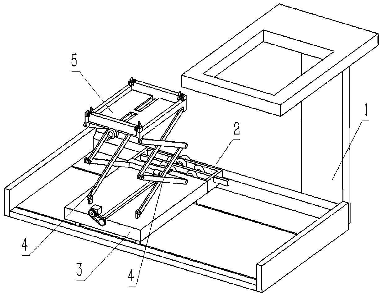
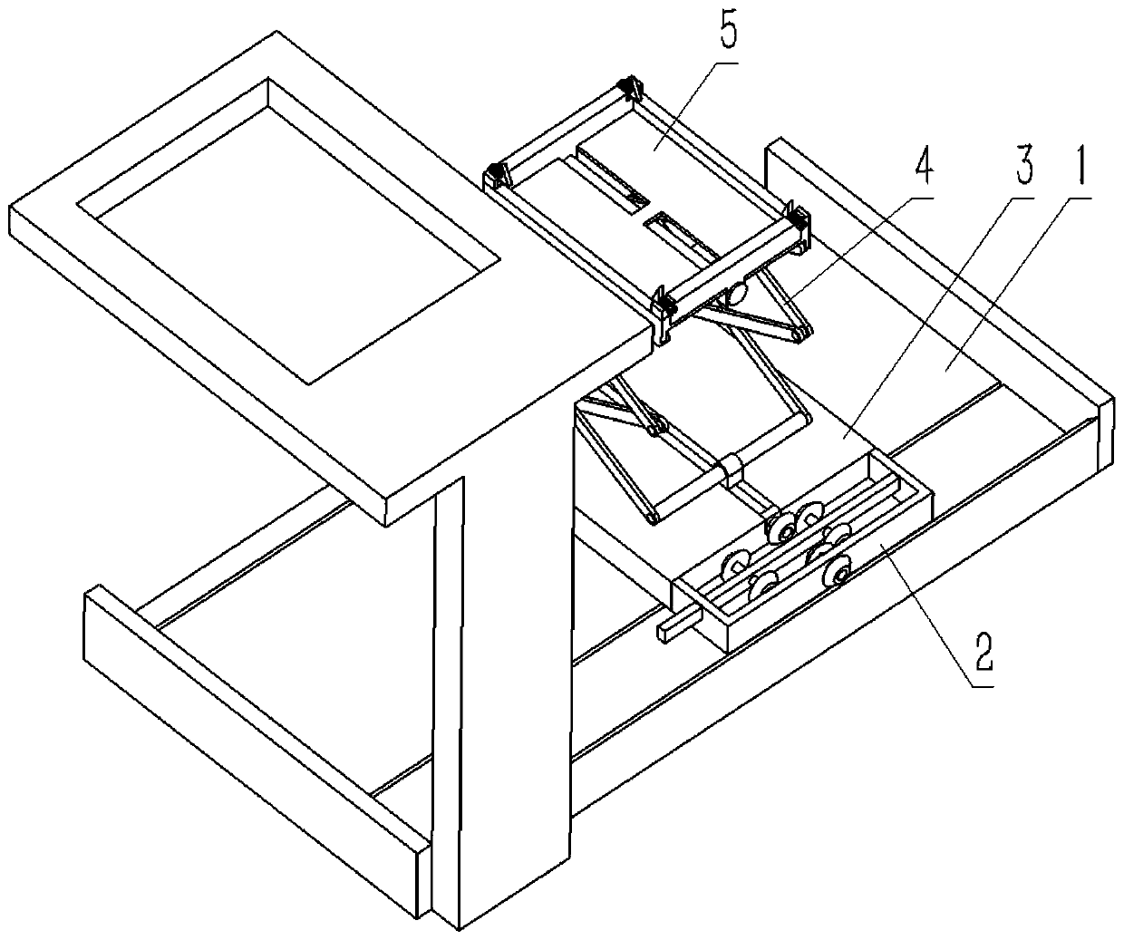
[0036] Combine below Figure 1-18 Describe this embodiment, an electric vehicle power exchange device, including a vehicle bracket 1, a sliding transmission combination 2, a sliding plate 3, two truss structures 4 and a bearing combination 5, the sliding transmission combination 2 includes an outer frame 2-1 , Rectangular slider 2-2, bevel gear Ⅰ2-3, transmission shaft Ⅰ2-4, bevel gear Ⅱ2-5, bevel gear Ⅲ2-6, transmission shaft Ⅱ2-7, bevel gear Ⅳ2-8, output bevel gear 2-9 , output transmission shaft 2-10, transmission bevel gear 2-11, rotating hole 2-12, two rectangular sliding holes 2-13 and two rectangular rod rotating holes 2-14, rotating hole 2-12 is arranged on the outer frame 2- 1. At the rear end of the inner wall, two rectangular sliding holes 2-13 are respectively arranged at the left and right ends of the inner wall of the outer frame 2-1. The inner end of the outer frame 2-1 is hollowed out, and two rectangular rods are arranged on the rectangular sliding rod 2-2. R...

specific Embodiment approach 2

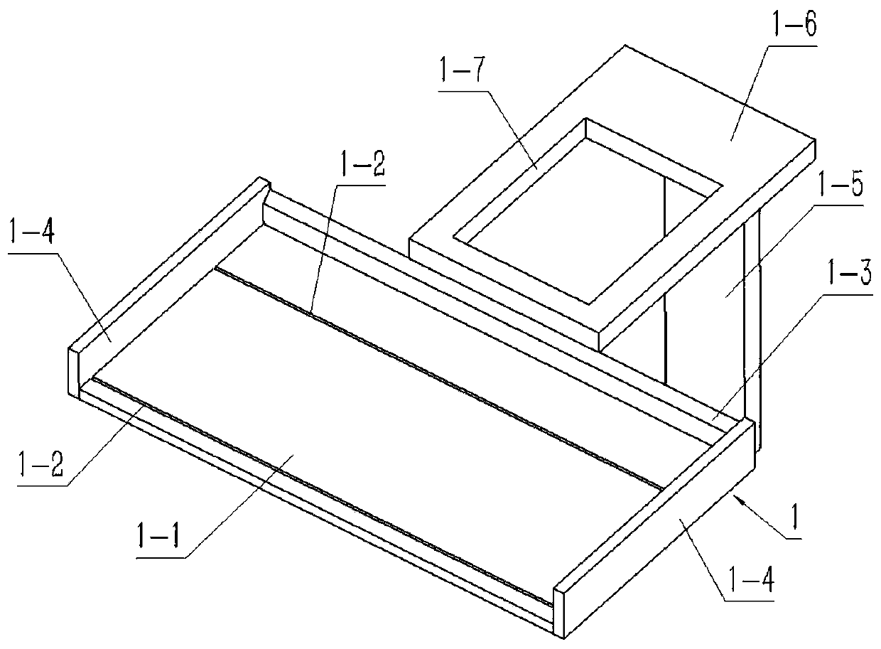
[0045] Combine below Figure 1-18 Describe this embodiment, this embodiment will further explain the first embodiment, the vehicle bracket 1 includes a bottom plate 1-1, two rectangular chute 1-2, an inclined rack plate 1-3, two end plates 1- 4. The support rod 1-5, the upper plate 1-6 and the rectangular through hole 1-7, the two rectangular chute 1-2 are evenly arranged on the upper end surface of the bottom plate 1-1, and the inclined rack plate 1-3 is fixedly connected to the The rear end of the base plate 1-1, the two end plates 1-4 are respectively fixedly connected to the left and right ends of the base plate 1-1, the pole 1-5 is fixedly connected to the right side of the rear end surface of the base plate 1-1, and the upper plate 1- 6 is fixedly connected to the upper end of the pole 1-5, and the rectangular through hole 1-7 is arranged on the upper plate 1-6;

[0046] The bottom plate 1-1 can be conveniently provided with two rectangular chute 1-2; the two rectangula...


PUM


Abstract

The invention relates to a power exchange device, more specifically to an electric vehicle power exchange device, which can realize automatic replacement of a rechargeable battery of an automobile, does not need to be replaced manually, and has low improvement efficiency. The power exchange device comprises a carrier bracket, a sliding transmission combination, a sliding plate, two truss structures and a bearing combination, and two rectangular sliding slots can be conveniently arranged on a bottom plate. The two rectangular sliding grooves can facilitate the sliding connection of the four lower sliders. The inclined rack plate can be conveniently meshed with the output cone tooth. The two end plates can restrict the sliding of the four lower sliders in the two rectangular sliding slots sothat the lower sliders do not break away from the rectangular sliding slots. The upper plate can be conveniently provided with a rectangular through hole; The supporting rod can facilitate the fixedconnection between the bottom plate and the upper plate; The rotating hole can facilitate the rotating connection of the output drive shaft; The output drive shaft can facilitate the fixed connectionof the transmission cone tooth and the output cone tooth; The drive shaft II can facilitate the fixed connection between the cone tooth IV and the cone tooth III. The drive shaft Ican be convenientlyconnected with the cone tooth II and the cone tooth I.

Description

technical field [0001] The invention relates to a battery exchange device, more specifically to an electric vehicle battery exchange device. Background technique [0002] For example, the patent No. is CN201510504102.1, an electric vehicle battery replacement device. Its technical characteristics are: it includes a car body, a lifting device and a battery replacement box. The battery replacement box is installed on the car body through a lifting device. A wheel, a high-definition camera is installed on the upper end of one side of the battery replacement box, two mechanical arms and a battery tray are installed under the high-definition camera, batteries, PLC control units, walking motors, Elevator controller, smart chip, video acquisition module, remote control module, reducer and access battery motor, which can be conveniently moved to the battery rack or electric vehicle by controlling the car body, and adjust the height of the mechanical arm through the lifting device. ...

Claims


Application Information

Patent Timeline
Patent Type & Authority Patents(China)
IPC IPC(8): B60L53/80B60S5/06
CPCB60S5/06Y02T10/70Y02T10/7072
Inventor 刘敦楠王文康海霞
Owner NORTH CHINA ELECTRIC POWER UNIV (BAODING)
Why Eureka
Try Eureka