
A power supply protection circuit

A technology for protecting circuits and circuits, applied in emergency protection circuit devices, electrical components, etc., can solve problems such as voltage drop, load voltage breakdown, damage to energy supply modules, etc., to protect the load and prevent damage.

Active Publication Date: 2020-10-23
BEIJING PINGGAO QINGDA TECH DEV CO LTD +3
View PDF7 Cites 0 Cited by
  • Summary
  • Abstract
  • Description
  • Claims
  • Application Information

AI Technical Summary

Problems solved by technology

[0005] 1. The peak current and voltage of the energy supply module due to insufficient adjustment rate will damage the subsequent control circuit;
[0006] 2. The output adjustment rate of the energy supply module is too low, resulting in a voltage drop when the load of the power electronic module changes rapidly;
[0007] 3. The energy supply module is damaged due to short circuit when the load control circuit of the power electronic module is out of control;
[0008] 4. Due to the lack of targeted on-site parameter setting capabilities of the general energy supply circuit, the output characteristics are poorly consistent when the load changes suddenly;
[0009] 5. When the internal control voltage stabilization circuit of the existing energy supply module fails, due to its current source characteristics, there is an abnormal increase in the output voltage when the load is low or no load, causing a risk of voltage breakdown to the load

Method used


Image

  • A power supply protection circuit
  • A power supply protection circuit
  • A power supply protection circuit

Examples


Embodiment Construction

[0037] In order to make the object, technical solution and advantages of the present invention clearer, the present invention will be further described in detail below in conjunction with the accompanying drawings and specific embodiments.

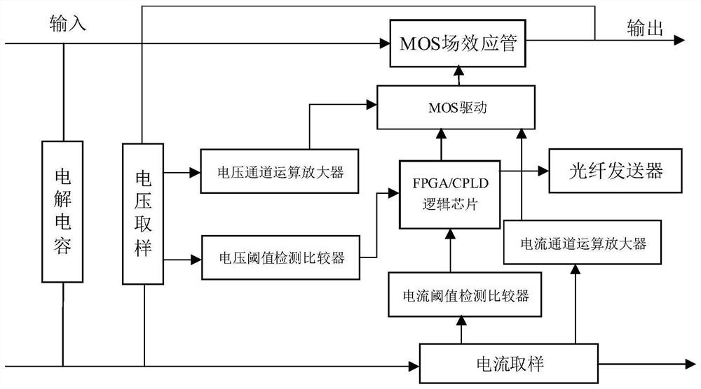
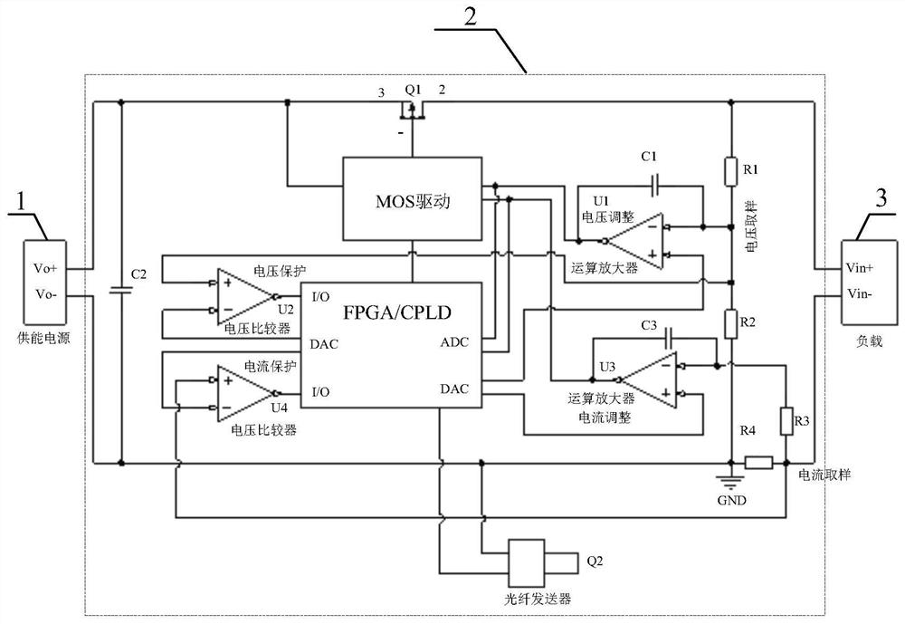
[0038] The invention provides an energy supply protection circuit. The energy supply protection device can be added or embedded into the design of the existing energy supply circuit (energy supply module) as a sub-circuit module, and can also be externally connected between the energy supply circuit and the energy supply circuit. The load acts as a middleware, that is, an adaptive series impedance, which serves the purpose of automatically protecting the energy supply circuit and the final load. For example, when the energy supply circuit is the energy-taking circuit (energy supply power supply) 1 of the power electronic device control circuit, and the load is the power electronic device control circuit 3, figure 1 Specifically, the positi...


PUM


Abstract

The invention relates to an energy supply protection circuit. The energy supply protection circuit comprises a circuit input port used for connecting an energy supply circuit, a circuit output port used for connecting a load, a power switch connected in series between the circuit input port and the circuit output port, and a power switch control circuit, wherein the power switch control circuit isin control connection with the power switch, a voltage sampling circuit, a voltage integral operation amplifying circuit and a controller are further comprised, the voltage sampling circuit is in sampling connection with the circuit output port and is used for obtaining the voltage of the circuit output port, a signal output end of the voltage sampling circuit is connected with an input end of the voltage integral operation amplifying circuit, an output end of the voltage integral operation amplifying circuit is connected with the power switch control circuit, and the controller is connectedwith the input end and the output end of the voltage integral operation amplifying circuit. The energy supply protection circuit is advantaged in that through controlling the conduction degree of thepower switch connected in series between the energy supply circuit and the load, so the purpose of stabilizing and limiting the output voltage of the energy supply circuit is achieved, and the load iseffectively protected.

Description

technical field [0001] The invention relates to an energy supply protection circuit, which belongs to the technical field of direct current transmission. Background technique [0002] The core device of the high-voltage DC circuit breaker is the power electronic device. In practical applications, the power electronic device forms a power electronic module, and the power electronic module realizes high potential through series connection. Each power electronic module needs to have its corresponding driving circuit, and the driving circuit and the power electronic module are directly connected electrically and are at the same potential. If the drive circuit wants to obtain energy, it can only obtain energy at a high level, or supply energy from a low potential through isolation. [0003] For high-voltage DC circuit breakers, because the capacitor of a single power electronic module does not store energy when it is closed, it cannot achieve high-level self-energy extraction, a...

Claims


Application Information

Patent Timeline
Patent Type & Authority Patents(China)
IPC IPC(8): H02H7/26
CPCH02H7/268
Inventor 张龙王留菊钟建英程铁汉张军民高树同陈玉峰
Owner BEIJING PINGGAO QINGDA TECH DEV CO LTD
Learn More