
Semiconductor diode chip structure and lamp illumination component thereof

A chip structure and semiconductor technology, applied in the direction of semiconductor devices, electrical components, cooling/heating devices of lighting devices, etc., can solve the problems of chip short circuit, affecting the accuracy of packaging, solder overflow, etc., and achieve the effect of improving luminous efficiency

Inactive Publication Date: 2018-12-07
北京敬一科技有限公司
View PDF7 Cites 0 Cited by
  • Summary
  • Abstract
  • Description
  • Claims
  • Application Information

AI Technical Summary

Problems solved by technology

[0003] The traditional front-mounted structure LED technology is slowly being eliminated, replaced by the flip-chip LED technology with better reliability and higher lumen density. At the same time, most of the existing semiconductor diode chips are packaged with epoxy resin. , the semiconductor diode chip is solidified by silica gel dispensing, and the sedimentation of the phosphor powder produced during the dispensing of silica gel makes the packaging effect uneven, and the light output effect of the LED is difficult to be well controlled. The flip-chip structure When connecting the positive and negative poles of the chip, the connection line is too long, which will easily affect the accuracy of the package. During the soldering process of the flip-chip diode chip, because the electrode faces downward, the alignment of the chip and the soldering point needs to be more precise. The packaging equipment is put into use, and the positive and negative electrodes are arranged on the same plane and with small intervals. It is also prone to chip short circuit caused by solder overflow during soldering.

Method used


Image

  • Semiconductor diode chip structure and lamp illumination component thereof
  • Semiconductor diode chip structure and lamp illumination component thereof
  • Semiconductor diode chip structure and lamp illumination component thereof

Examples


Embodiment 2

[0061] Such as Figure 10 As shown, the present invention also provides a semiconductor diode chip packaging manufacturing method, comprising the following steps:

[0062] S100, welding the metal heat sink to the package bracket, and fixing the chip position.

[0063] S200. The packaging bracket with the chip installed is sent to the reflow furnace for reflow soldering. During the reflow soldering, the temperature in the reflow furnace rises rapidly to the preheating temperature, and then continues to heat up to the melting temperature of the solder to produce a melting reaction. Finally, the temperature is rapidly lowered. .

[0064] S300. Connect the positive and negative poles of the chip with the metal pins on the package support, and weld the metal pins on the package support.

[0065] S400, dispensing the hemispherical silica gel on the surface of the chip, and installing the overall connection structure of the reflective cup and the negative lens.

[0066] Wherein st...


PUM


Abstract

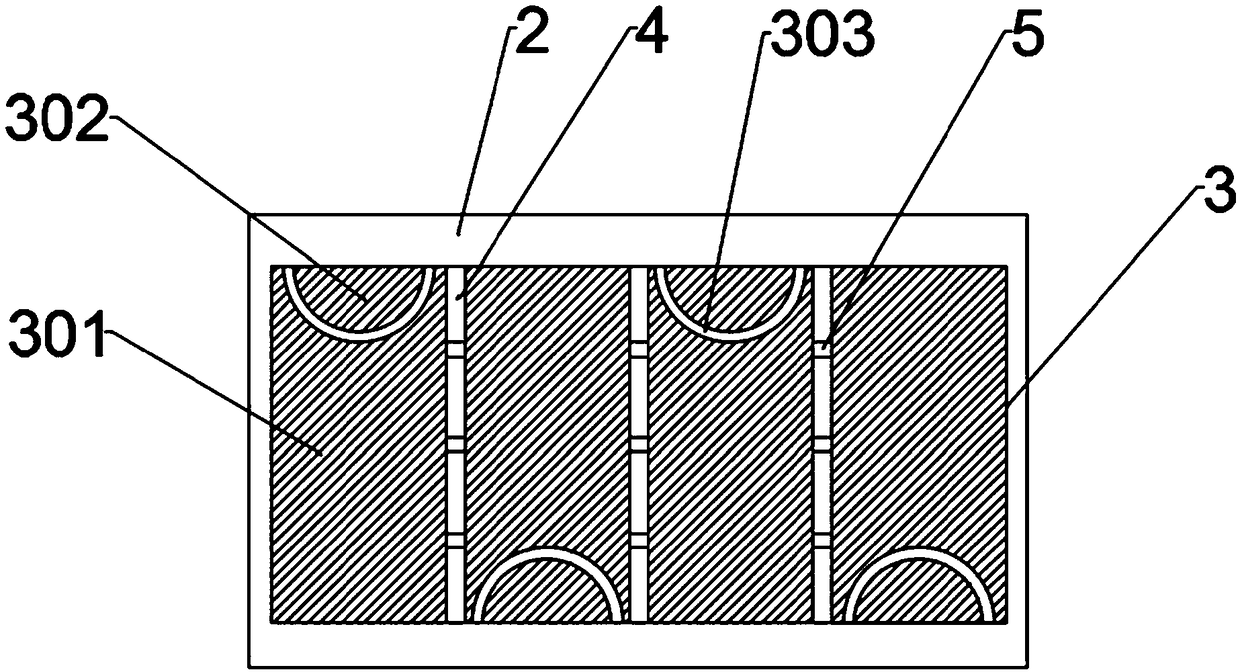
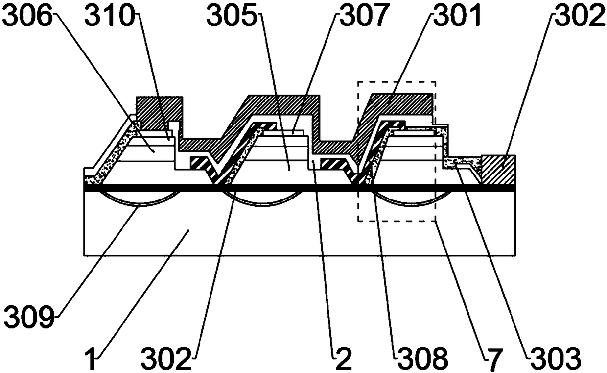
The invention discloses a semiconductor diode chip structure. The structure comprises a semiconductor diode chip, the packaging structure of the semiconductor diode chip, and the substrate of a weldedpackaging structure. The semiconductor diode chip comprises a sapphire substrate. The sapphire substrate is provided with a square-shaped packaging insulating layer. The sapphire substrate in the packaging insulating layer is filled with several main chip units. Fine seam grooves are arranged between the adjacent main chip units. Each main chip unit comprises a first metal disc. One side of the first metal disc is provided with a second metal disc. An annular insulating layer is arranged between the second metal disc and the first metal disc. The installation positions of the second metal discs on the two adjacent main chip units are opposite. The two ends of the annular insulating layer are connected to the packaging insulating layer. Connection bridges are arranged in the fine seam grooves. The connection bridges are provided with micro chips. The separated work and the excitation type combination of a chip structure are realized, and the total light output of a main unit chip is increased.

Description

technical field [0001] The invention relates to the field of semiconductor diodes, in particular to a semiconductor diode chip structure and a lighting assembly thereof. Background technique [0002] In the field of semiconductor diodes, LED is an important photoelectric diode. LED technology is gradually replacing traditional lighting technology and fluorescent technology and entering the lighting field. At the same time, LED chips also have the characteristics of electronic devices. In the process of the pursuit of higher lumens and the continuous compression of industrial manufacturing costs, the flip-chip application of light-emitting diodes has been generally considered to be an industry trend. Flip-chip light-emitting diode chips are beneficial to obtain higher currents. High lumen value, and improve the heat conduction of the chip by soldering the heat sink closer to the semiconductor active area. [0003] The traditional front-mounted structure LED technology is slo...

Claims


Application Information

Patent Timeline
IPC IPC(8): H01L33/48H01L33/62H01L33/46F21V29/67F21V29/77
CPCF21V29/67F21V29/77H01L33/46H01L33/48H01L33/62
Inventor 张娟
Owner 北京敬一科技有限公司
Learn More