A local magnetization device

A magnetization device and local technology, applied in the direction of measuring device, material magnetic variable, material analysis through electromagnetic means, etc., can solve the problems of short support base plate length, small size range of workpiece, difficult to control probe gap and axis, etc., to achieve increase Probe fine-tuning structure, convenient on-site installation, convenient on-site debugging effect

Active Publication Date: 2020-05-15
EDDYSUN (XIAMEN) ELECTRONICS CO LTD
View PDF7 Cites 0 Cited by
  • Summary
  • Abstract
  • Description
  • Claims
  • Application Information

AI Technical Summary

Problems solved by technology

[0002] The local magnetization device is a commonly used device in the eddy current flaw detection of the quality of ferromagnetic tubes and bars in the metallurgical industry. It is used to magnetize the workpiece to be inspected and improve the sensitivity of eddy current detection. The existing local magnetization device has the following shortcomings: the length of the lower support base is too short, The probe and coil are suspended at the front end, causing the equipment to tilt to one side during storage and installation; the probe is under the magnetized coil, and it is inconvenient to operate when replacing the probe and magnetic shoe, and it is difficult to control the gap and axis of the probe, magnetic shoe and workpiece. The size range of the workpiece to be detected is small; the structure of the lifting part of the cylinder requires high processing and installation precision. If the processing and installation are not in place, it is easy to cause jams; the rollers at both ends of the magnetic arm are not positioned, and it is difficult for the workpiece to Keep in line with the axis of the probe and magnetic shoe

Method used


Image

  • A local magnetization device
  • A local magnetization device
  • A local magnetization device

Examples


Embodiment 1

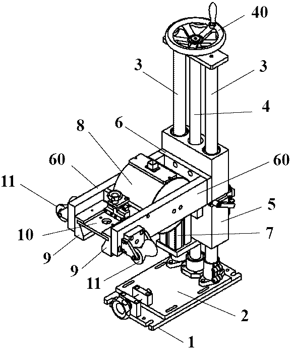
[0026] Example 1, such as figure 1 , 2 , 3, and 4, a local magnetization device includes a base 1, a lateral adjustment plate 2, a pillar 3, a threaded transmission shaft 4, a lifting bracket 5, a yoke 6, a cylinder 7, a magnetization coil 8, a magnetic shoe 9, and a probe Fixed adjusting frame 10, guide wheel 11 are characterized in that:

[0027] The horizontal adjustment plate 2 is fixed on the upper surface of the base 1, and the lateral adjustment movement of the horizontal adjustment plate 2 on the upper surface of the base 1 is controlled by adjusting the adjustment mechanism on the horizontal adjustment plate 2;

[0028] There are two pillars 3, which are vertically fixed on the upper surface of the horizontal adjustment plate 2 side by side;

[0029] The threaded transmission shaft 4 is vertically fixed on the upper surface of the lateral adjustment plate 2 between the two pillars 3, the top of the threaded transmission shaft 4 is fixed with a hand wheel 40, and the...

Embodiment 2

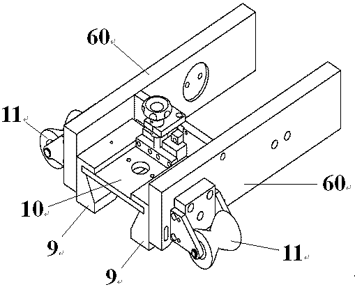
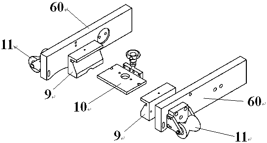
[0036] Example 2, such as Figure 5 , 6 As shown, further, the cylinder 7 is fixed on the lifting bracket 5, the piston rod 70 of the cylinder 7 is downward, and the moving direction of the piston rod 70 of the cylinder 7 is parallel to the pillar 3; the yoke 6 is fixed on the piston below the cylinder 7 The top 71 of the rod 70, the pillar 3 passes through the yoke 6, the two arms 60 of the yoke 6 are perpendicular to the pillar 3, the cylinder 7 controls the yoke 6 to move back and forth along the pillar 3 through the piston rod 70, and the piston rod 70 of the cylinder 7 moves downward When the yoke 6 is fixed below it, the cylinder 7 controls the reciprocating movement range of the yoke 6 to be small, which can be used to detect workpieces with small diameters.


PUM


Abstract

The invention discloses a local magnetization device comprising a base, a lateral adjusting plate, a pillar, a threaded driving shaft, a lifting bracket, a magnet yoke, an air cylinder, a magnetizingcoil, a magnetic boot, a probe frame and a guiding wheel, compared with the existing local magnetization device, the local magnetization device has the following advantages: the lateral adjusting mechanism is added to facilitate fine adjustment during field installation; the center of gravity of the entire device falls within the range of the base, and the device is not tilted to one side during storage and installation, facilitating on-site installation; a probe fine adjustment structure is added for accurately controlling the clearance between a probe and a workpiece, the magnetic boot can be installed and fixed by a clamping groove mode, the specification of the magnetic boot can be quickly changed, and time is saved; the air cylinder is set below the magnetic boot, the stroke of the air cylinder is increased, detection requirements of a larger pipe diameter can be met, and the local magnetization device is convenient for on-site debugging.

Description

technical field [0001] The invention relates to a non-destructive testing device, in particular to a local magnetization device. Background technique [0002] The local magnetization device is a commonly used device in the eddy current flaw detection of the quality of ferromagnetic tubes and bars in the metallurgical industry. It is used to magnetize the workpiece to be inspected and improve the sensitivity of eddy current detection. The existing local magnetization device has the following shortcomings: the length of the lower support base is too short, The probe and coil are suspended at the front end, causing the equipment to tilt to one side during storage and installation; the probe is under the magnetized coil, and it is inconvenient to operate when replacing the probe and magnetic shoe, and it is difficult to control the gap and axis of the probe, magnetic shoe and workpiece. The size range of the workpiece to be detected is small; the structure of the lifting part of...

Claims


Application Information

Patent Timeline
Patent Type & Authority Patents(China)
IPC IPC(8): G01N27/90
CPCG01N27/9006
Inventor 林俊明石银河吴玉宗赵晋成
Owner EDDYSUN (XIAMEN) ELECTRONICS CO LTD
Why Eureka
Try Eureka