
Oscillating mechanism of internal grinding machine

An oscillating mechanism, the technology of an internal cylindrical grinder, which is applied in the directions of grinding machine parts, grinding machines, and machine tools designed for grinding the rotating surface of workpieces, can solve problems such as affecting work efficiency and large vibration.

Inactive Publication Date: 2018-12-07
LUOYANG INST OF SCI & TECH
View PDF6 Cites 3 Cited by
  • Summary
  • Abstract
  • Description
  • Claims
  • Application Information

AI Technical Summary

Problems solved by technology

In the machinery industry, the earliest oscillating mechanisms are all eccentric wheel mechanisms. In actual work, with the change of vibration frequency and amplitude, the vibration generated by the equipment itself is different. The greater the amplitude of the oscillating mechanism, the greater the vibration of the equipment itself. , affecting work efficiency

Method used


Image

  • Oscillating mechanism of internal grinding machine
  • Oscillating mechanism of internal grinding machine
  • Oscillating mechanism of internal grinding machine

Examples


specific Embodiment approach

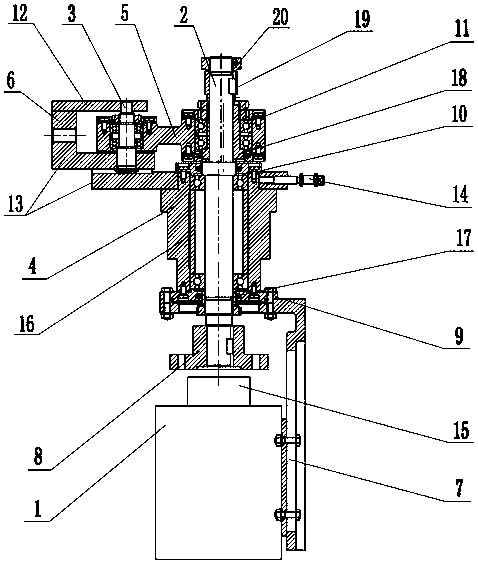
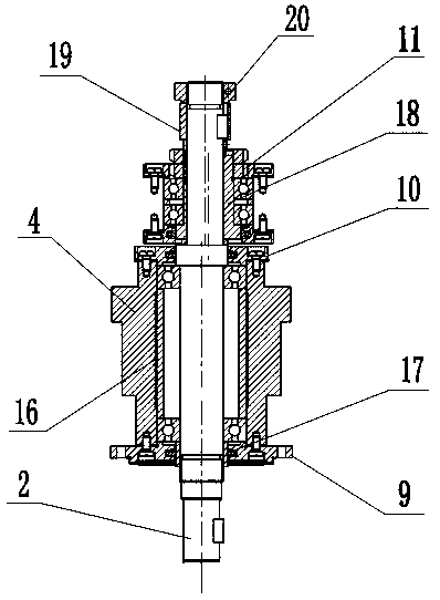
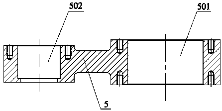
[0023] An oscillating mechanism of an internal grinding machine, structurally, includes a motor 1, an eccentric shaft 2, a small shaft 3, a shaft sleeve 4, a connecting rod 5, a supporting plate 6 and a positioning bracket 7, and the positioning bracket 7 includes an inverted The longitudinal connection plate 701 and the horizontal connection plate 702 of the L-shaped connection, the eccentric shaft positioning hole 703 is arranged on the horizontal connection plate 702, the motor 1 is fixed on the inside of the longitudinal connection plate 701 by screws, and the motor 1 is fixed on the inner side of the longitudinal connection plate 701. A reducer 15 is provided, and the motor 1 is a Y200L-4 three-phase asynchronous motor; the eccentric shaft 2 passes through the eccentric shaft positioning hole 703, and is connected to the motor 1 through a coupling 8;

[0024] Above the horizontal connecting plate 702, there are bearing end cover I9, bearing end cover II10 and bearing end c...


PUM


Abstract

The invention discloses an oscillating mechanism of an internal grinding machine. The oscillating mechanism of the internal grinding machine comprises a motor, an eccentric shaft, a small shaft, a shaft sleeve, a connecting rod, a supporting plate and a positioning support. An eccentric shaft positioning hole is formed in a horizontal connecting plate of the positioning support; a bearing end cover I, a bearing end cover II and a bearing end cover III are disposed in sequence above the horizontal connecting plate of the positioning support; the shaft sleeve is disposed between the bearing endcover I and the bearing end cover II; the connecting rod is disposed between the bearing end cover II and the bearing end cover III; the eccentric shaft sequentially penetrates through the bearing endcover III, a shaft hole I, the bearing end cover II, the shaft sleeve, the bearing end cover I and the eccentric shaft positioning hole to be connected with the motor though a coupler; the supportingplate comprises an upper supporting plate body, an L-shaped plate body and an adjusting plate body; a shaft hole III is formed in the upper supporting plate body; a shaft hole IV is formed in one horizontal end of the L-shaped plate body; the small shaft sequentially penetrates through the shaft hole III, the shaft hole I and the shaft hole IV to connect the supporting plate with the connecting rod; and an adjusting screw rod is disposed on the adjusting plate body. By means of reduction of self oscillating of the internal grinding machine, the requirement of high-speed grinding is met, and the surface quality and grinding efficiency of ground workpieces can be improved.

Description

technical field [0001] The invention relates to the field of agricultural machinery, in particular to an oscillation mechanism of an internal grinder. Background technique [0002] With the emergence of machine tools, the number of various special-purpose machine tools has gradually increased, and different special-purpose machine tools will be used to process different structures for different parts. The internal grinding machine is one of the special machine tools. The production of the internal grinding machine is due to the continuous increase in various processing needs in today's society. As the name implies, the internal grinding machine is used to grind various high-precision round holes and Some parts that require high internal precision. The internal difference of the oscillating reciprocating system in the internal grinding machine determines the grinding accuracy to a great extent. However, the development of the reciprocating mechanism is far behind the require...

Claims


Application Information

Patent Timeline
Patent Type & Authority Applications(China)
IPC IPC(8): B24B5/06B24B47/12
CPCB24B5/06B24B47/12
Inventor 李彬李小康郝勇任睿卓李军伟景凯亮王红
Owner LUOYANG INST OF SCI & TECH
Learn More