Unmanned aerial vehicle plasma flow control flight test measurement and control system

A plasma and flight test technology, which is applied in the field of plasma flow control UAV flight test measurement and control system, can solve the problems of incomplete flow field data measurement and collection, and cannot quantitatively reflect the plasma flow control effect, etc., to achieve weakening Effects of Electromagnetic Interference

Active Publication Date: 2018-12-04
AIR FORCE UNIV PLA
View PDF8 Cites 0 Cited by
  • Summary
  • Abstract
  • Description
  • Claims
  • Application Information

AI Technical Summary

Problems solved by technology

At present, the flight test of plasma flow control is in its infancy. The switching of the plasma actuator during the flight, the measurement and collection of flow field data are not perfect, and cannot quantitatively reflect the effect of plasma flow control.

Method used


Image

  • Unmanned aerial vehicle plasma flow control flight test measurement and control system
  • Unmanned aerial vehicle plasma flow control flight test measurement and control system
  • Unmanned aerial vehicle plasma flow control flight test measurement and control system

Examples


Embodiment Construction

[0037] Below in conjunction with accompanying drawing, the present invention is described in further detail:

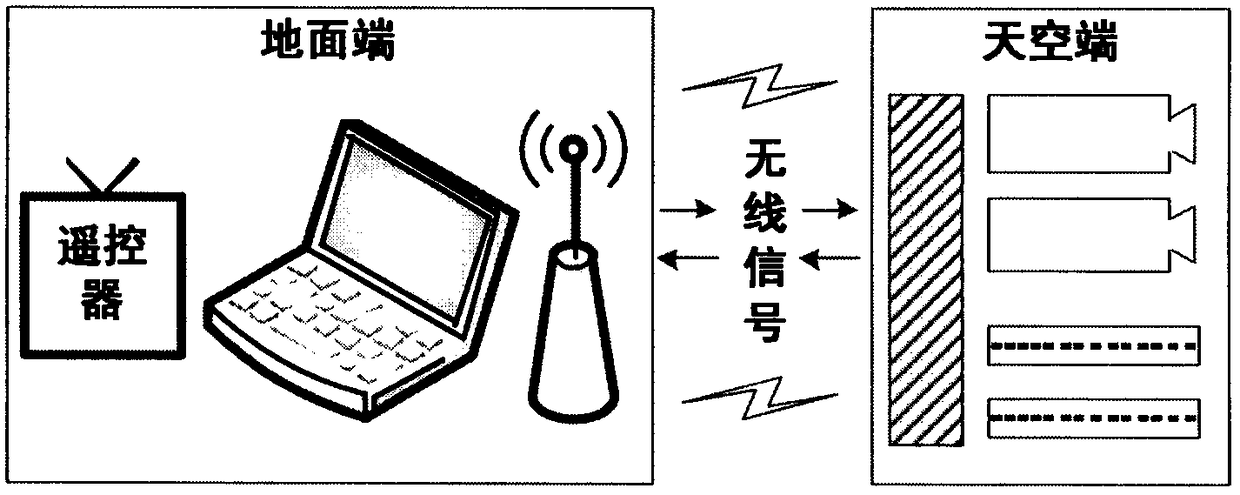
[0038] like figure 1 As shown, the plasma flow control UAV flight test measurement and control system includes two parts: the sky end and the ground end, and the two parts are connected by wireless signals. The operator inputs commands at the ground terminal, the ground terminal converts the command into a wireless signal and sends it to the sky terminal, and the sky terminal receives the command and executes corresponding operations; after the sky terminal measures the required data (such as pressure data, image data, etc.), it also The data is converted into a wireless signal and sent to the ground terminal, and the ground terminal receives the signal and displays the data contained in the signal.

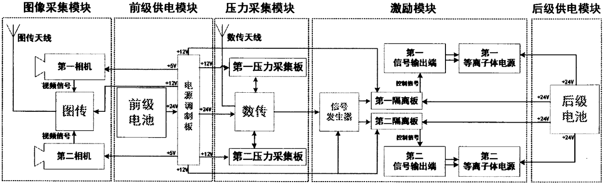
[0039] The structure of the sky end is as figure 2 As shown, it includes an image acquisition module, a pre-stage power supply module, a pressure acquisition module, ...


PUM


Abstract

The invention provides an unmanned aerial vehicle plasma flow control flight test measurement and control system which comprises two parts of a sky end and a ground end which are connected through wireless signals. An operator inputs a command into the ground end, the ground end converts the command into the wireless signal and sends the wireless signal to the sky end, and the sky end receives thecommand and executes corresponding operation; and after the sky end measures required data, the sky end converts the data into the wireless signal and sends the wireless signal to the ground end, theground end receives the signal and displays the data contained in the signal. The system can remotely control on-off and parameter change of an onboard plasma power source in the flight process of anunmanned aerial vehicle, record and transmit an airfoil image and an airfoil pressure distribution condition back in real time and test a flow control effect.

Description

technical field [0001] The invention relates to plasma flow control technology, in particular to a plasma flow control UAV flight test measurement and control system. Background technique [0002] The wing is a key component of the aircraft, providing more than 70% of the total lift for the aircraft, and its performance directly determines the aerodynamic performance of the entire aircraft. When the angle of attack of the aircraft is large, the suction surface of the wing will cause the separation of the boundary layer, which will reduce the lift and increase the drag. When the angle of attack exceeds the critical angle of attack, the boundary layer is severely separated, the lift of the wing decreases sharply, the drag increases rapidly, and the aircraft stalls. How to suppress the separation of the wing boundary layer and improve the performance of the aircraft has always been an important issue in the aviation field. [0003] Plasma flow control technology is a new type...

Claims


Application Information

Patent Timeline
Patent Type & Authority Applications(China)
IPC IPC(8): B64F5/60
CPCB64F5/60
Inventor 吴云魏彪梁华贾敏宋慧敏金迪苏志谢理科
Owner AIR FORCE UNIV PLA
Why Eureka
Try Eureka