
Cascade connection robust fault-tolerance forecast control method for permanent magnet synchronous motor

A permanent magnet synchronous motor, predictive control technology, applied in the direction of motor control, motor generator control, electronic commutation motor control, etc., can solve problems affecting reliability, permanent magnet demagnetization, predictive control motor system parameter changes, etc., to achieve The effect of improving the effect, eliminating parameter perturbation, improving control accuracy and reliability of operation

Active Publication Date: 2018-11-30
HUNAN UNIV
View PDF5 Cites 6 Cited by
  • Summary
  • Abstract
  • Description
  • Claims
  • Application Information

AI Technical Summary

Problems solved by technology

However, the PI controller has the following disadvantages. First, the parameter setting of the PI controller only corresponds to a certain working range
Therefore, when the working state of the motor changes, the control effect of the PI controller cannot be optimal
Second, the permanent magnet synchronous motor system is a nonlinear system with parameter changes, and there is a risk of permanent magnet demagnetization
Although predictive control has many advantages, predictive control is easily affected by changes in motor system parameters
The perturbation of the parameters and the demagnetization of the permanent magnet synchronous motor during the operation of the permanent magnet synchronous motor will reduce the control accuracy of the permanent magnet synchronous motor and affect the reliability of its operation

Method used


Image

  • Cascade connection robust fault-tolerance forecast control method for permanent magnet synchronous motor
  • Cascade connection robust fault-tolerance forecast control method for permanent magnet synchronous motor
  • Cascade connection robust fault-tolerance forecast control method for permanent magnet synchronous motor

Examples


Embodiment Construction

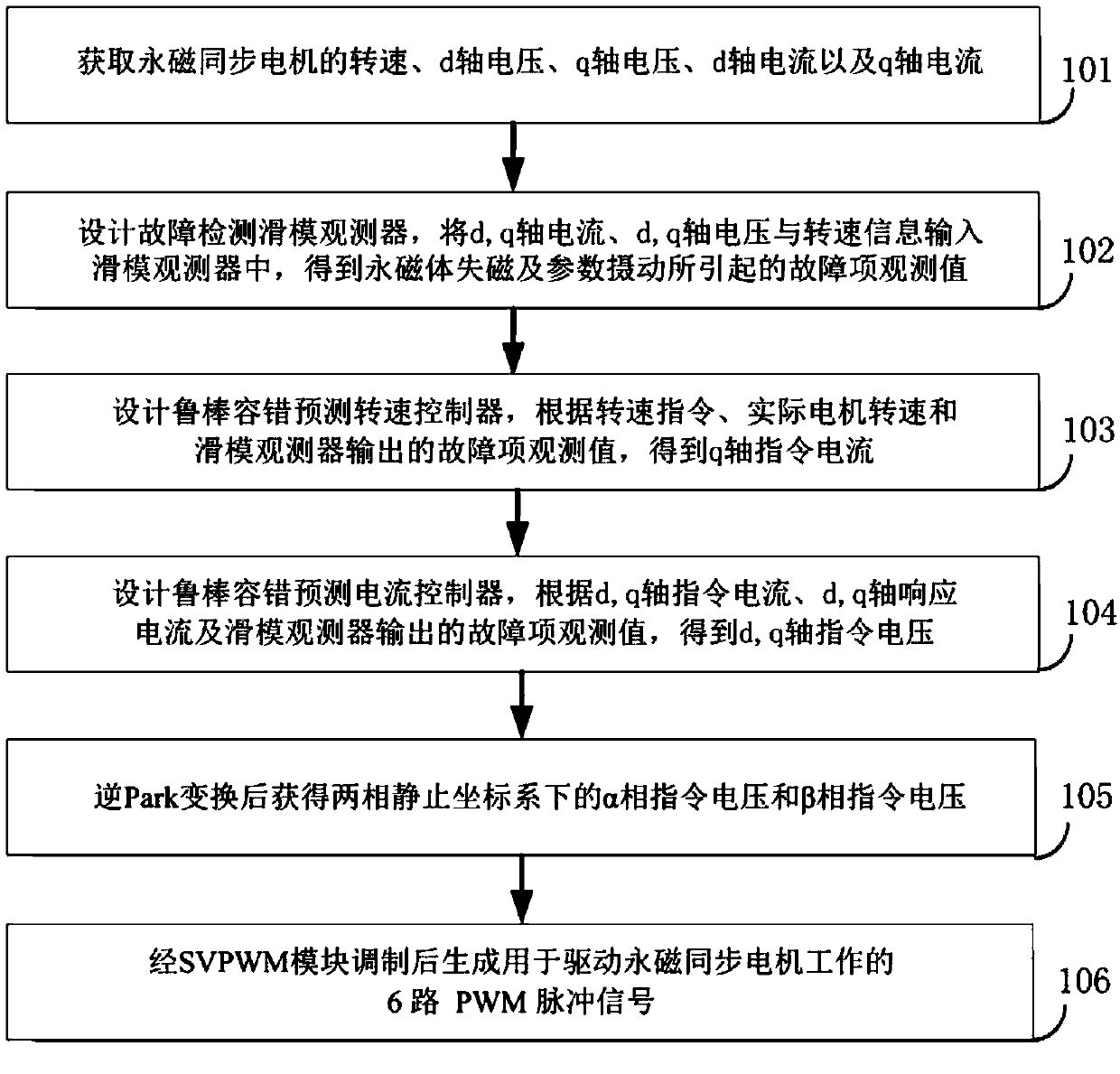
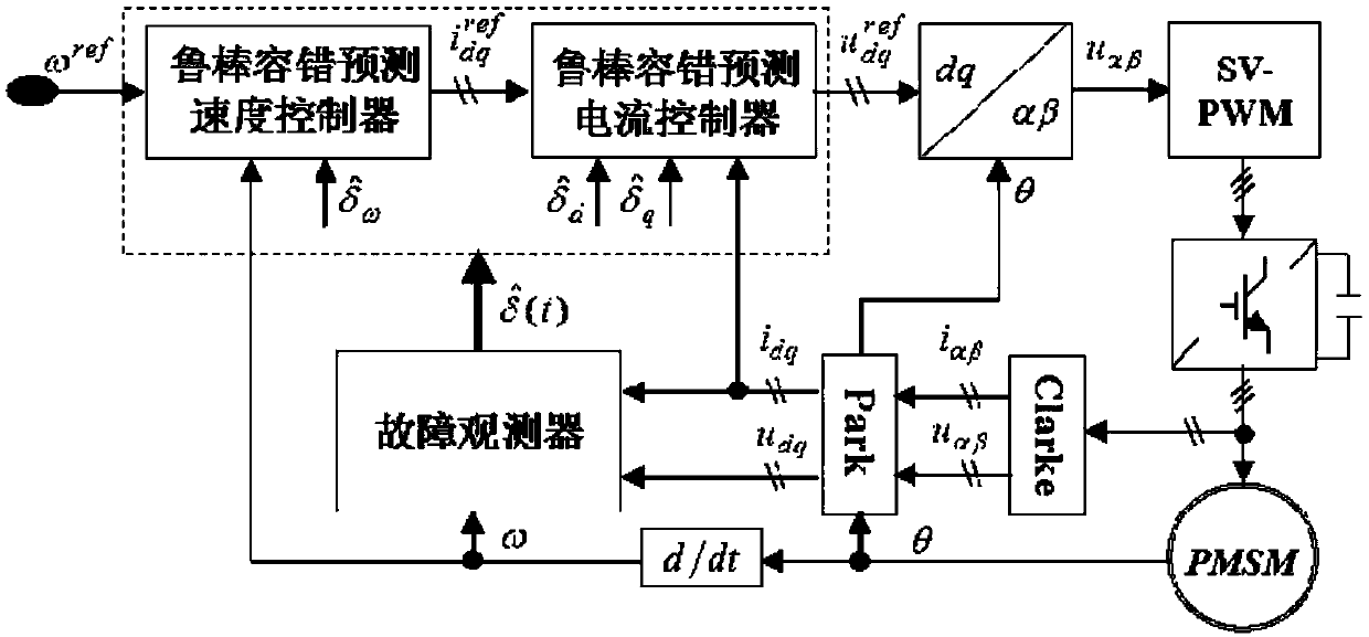
[0056] like figure 1 and figure 2 As shown, the implementation steps of a cascaded robust fault-tolerant predictive control method for permanent magnet synchronous motors in this embodiment include:

[0057] Step 1) Obtain the rotational speed ω and the d-axis voltage u of the permanent magnet synchronous motor d , q-axis voltage u q , d-axis current i d and the q-axis current i q ;

[0058] Step 2) Design the integral terminal sliding mode observer for fault detection, and take the rotational speed ω and the d-axis voltage u d , q-axis voltage u q , d-axis current i d and the q-axis current i q Input the fault detection integral terminal sliding mode observer to obtain the observed value of the fault term

[0059] The detailed steps of step 2) include:

[0060] 2.1) Establish the permanent magnet synchronous motor state equation under the parameter perturbation shown in formula (1) and the permanent magnet demagnetization fault situation;

[0061]

[0062] In...


PUM


Abstract

The invention discloses a cascade connection robust fault-tolerance forecast control method for a permanent magnet synchronous motor. The method comprises the following steps that the rotating speed,voltage and electric current of the permanent magnet synchronous motor are obtained; a fault detection integral terminal sliding mode observer is designed to obtain the observation value of fault items; a robust fault-tolerant forecast rotating speed controller is designed, and q-axis instruction current is calculated based on the given rotating speed, the response rotating speed and fault item observation value; a robust fault-tolerant forecast current controller is designed, and command voltage is calculated based on given current, response current and the fault item observation value; and PWM pulse signals are generated by inverse Park transformation and SVPWM module modulation, and therefore the permanent magnet synchronous motor is driven to work. Fast robust tracking with no static error of the rotating speed and electric current of the permanent magnet synchronous motor is achieved, and control accuracy and operation reliability of the permanent magnet synchronous motor are improved. Development of application of the permanent magnet synchronous motor in harsh environment and high reliability requirements is facilitated.

Description

technical field [0001] The invention relates to the control technology of a permanent magnet synchronous motor, in particular to a cascade robust fault-tolerant predictive control method of a permanent magnet synchronous motor. Background technique [0002] Permanent magnet synchronous motors have been widely used due to their advantages of simple structure, high efficiency and low failure rate. People have also put forward higher requirements on the control performance of permanent magnet synchronous motors. Vector control is the most commonly used method for high-performance control of permanent magnet synchronous motors, and the control of speed loop and current loop is the key. The traditional speed loop and current loop controllers are PI controllers, which are widely used in permanent magnet AC motor drives due to their simplicity and robustness. However, the PI controller has the following disadvantages. First, the parameter setting of the PI controller only corresp...

Claims


Application Information

Patent Timeline
IPC IPC(8): H02P21/00H02P21/24H02P21/22H02P21/14
CPCH02P21/0007H02P21/14H02P2207/05H02P21/22H02P21/24
Inventor 黄守道吴公平张昌凡吕铭晟罗德荣龙卓
Owner HUNAN UNIV
Learn More