Diffraction wave separation method and device

A diffracted wave and singular value decomposition technology, applied in the field of seismic exploration, can solve problems such as poor diffracted wave effect and diffracted wave distortion

Inactive Publication Date: 2018-11-30
CHINA UNIV OF MINING & TECH (BEIJING)
View PDF5 Cites 6 Cited by
  • Summary
  • Abstract
  • Description
  • Claims
  • Application Information

AI Technical Summary

Problems solved by technology

[0005] In view of this, the purpose of the present invention is to provide a diffraction wave separation method and device to alleviate the serious distortion of the diffraction wave obtained by the existing diffraction wave separation method, and the effect of the diffraction wave obtained after separation is not good. technical issues

Method used


Image

  • Diffraction wave separation method and device
  • Diffraction wave separation method and device
  • Diffraction wave separation method and device

Examples


Embodiment 1

[0060] According to an embodiment of the present invention, an embodiment of a diffracted wave separation method is provided. It should be noted that the steps shown in the flow charts of the accompanying drawings can be executed in a computer system such as a set of computer-executable instructions, and , although a logical order is shown in the flowcharts, in some cases the steps shown or described may be performed in an order different from that shown or described herein.

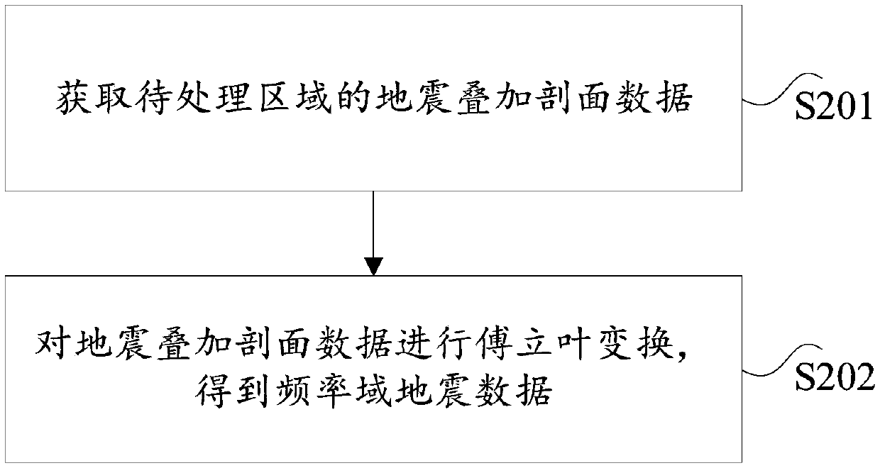
[0061] figure 1 is a flow chart of a diffraction wave separation method according to an embodiment of the present invention, such as figure 1 As shown, the method includes the following steps:

[0062] Step S102, acquiring frequency domain seismic data of the area to be processed;

[0063] In the embodiment of the present invention, the area to be processed is an area collected in the wild.

[0064] Step S104, performing singular value decomposition on the seismic data in the frequency domain, and per...

Embodiment 2

[0122] The embodiment of the present invention also provides a diffraction wave separation device, which is mainly used to implement the diffraction wave separation method provided in the above-mentioned content of the embodiment of the present invention. The separation device is introduced in detail.

[0123] Figure 7 is a schematic diagram of a diffraction wave separation device according to an embodiment of the present invention, such as Figure 7 As shown, the diffraction wave separation device mainly includes: an acquisition module 11, a decomposition calculation module 12, a first determination module 13 and a second determination module 14, wherein:

[0124] An acquisition module, configured to acquire frequency-domain seismic data in the region to be processed;

[0125] The decomposition calculation module is used to perform singular value decomposition on the frequency domain seismic data, and perform energy entropy calculation according to the decomposed singular ...


PUM


Abstract

The invention provides a diffraction wave separation method and a diffraction wave separation device. The method comprises the steps of acquiring frequency domain seismic data of an area to be processed; performing singular value decomposition on the frequency domain seismic data, and performing energy entropy computation on the decomposed singular value to acquire an energy entropy correspondingto each singular value; determining a diffraction wave singular value in the singular value based on the energy entropy, and determining a diffraction wave singular value vector corresponding to the diffraction wave singular value; and based on the diffraction wave singular value and the diffraction wav singular value vector, determining a target diffraction wave signal. According to the method provided by the invention, reflected waves can be effectively suppressed, meanwhile, the diffraction wave signal is protected, and finally the acquired target diffraction wave signal has good amplitudepreservation; the diffraction wave acquired after separation is good in effect, and the technical problems that the diffraction wave acquired via separation by using the existing diffraction wave separation method is seriously distorted, and the diffraction wave acquired after separation is poor in effect are relieved.

Description

technical field [0001] The invention relates to the technical field of seismic exploration, in particular to a diffraction wave separation method and device. Background technique [0002] Small-scale discontinuous geological bodies, such as faults, collapse columns, cracks, etc., are often closely related to the distribution of mineral resources. Accurate positioning of non-uniform and discontinuous geological bodies can effectively improve the success rate of exploration, reduce costs, and avoid possible occurrences. geological disasters and avoid risks. Diffraction waves are the seismic response of small-scale geological bodies, which contain structural information of small-scale geological bodies, and can be used to accurately locate non-uniform and discontinuous geological bodies and provide stronger underground space illumination. However, compared with the reflected wave, the diffracted wave attenuates faster and has weaker energy during the propagation process, and i...

Claims


Application Information

Patent Timeline
Patent Type & Authority Applications(China)
IPC IPC(8): G01V1/28
CPCG01V1/28
Inventor 林朋彭苏萍赵惊涛崔晓芹
Owner CHINA UNIV OF MINING & TECH (BEIJING)
Why Eureka
Try Eureka