
Direct heat absorption type energy storage power generation system based on vacuum heat absorbing tubes

A technology of a power generation system and a heat-absorbing tube is applied in the field of direct heat-absorbing energy storage power generation system, which can solve the problems of difficult cleaning and maintenance, deposition of dust and debris on the mirror surface, affecting the reflection and absorption of sunlight, etc., so as to reduce the difficulty of tracking adjustment. and cost, reducing tracking accuracy requirements, increasing power generation and revenue

Pending Publication Date: 2018-11-30
杨大楼
View PDF5 Cites 1 Cited by
  • Summary
  • Abstract
  • Description
  • Claims
  • Application Information

AI Technical Summary

Problems solved by technology

[0005] 1. In order to achieve high temperature in the traditional tower-type photothermal power generation system, the molten salt heat absorber on the top of the tower is small in size, resulting in extremely high control precision requirements for the heliostats; and due to the distance between each heliostat and the central tower and the With different orientations, the tracking of each heliostat requires separate two-dimensional control, which makes the heliostat tracker difficult to manufacture, high in cost, difficult to track and adjust, and difficult to maintain in the field application environment
[0006] 2. When the system is working, it needs to send the molten salt from the storage tank on the ground to the heat absorber on the top of the tower, which requires a high-lift molten salt pump; high power consumption
[0007] 3. Molten salt heating, heat storage, and power generation all need to circulate in the pipeline. Because molten salt has a high melting point, it is easy to solidify at low temperature. In the morning and evening, cloudy, cloudy and other conditions with weak light intensity, the temperature of molten salt is too low The solidification will cause the pipeline to be blocked and frozen, resulting in a decrease in the stability and reliability of the overall system and an increase in maintenance and repair costs.
[0008] 4. During periods of weak light intensity such as morning and evening, cloudy, cloudy, etc., the molten salt heat sink of the solar thermal power plant will no longer work, and the heliostat system will be idle, resulting in waste of resources
However, the secondary reflector system is affected by its own structure and severe weather such as strong winds in the field, so the area should not be enlarged. This requires high tracking accuracy of the heliostat, which is difficult to track and high in cost, which is not conducive to popularization and application.
At the same time, when the secondary reflector and quartz glass window are used in the field, they are easily affected by strong winds and other weather, causing dust and debris to be deposited on the mirror surface, making it difficult to guarantee cleanliness, which affects the reflection and absorption of sunlight; and the mirror surface is in a high temperature state during operation, making it difficult to clean and maintain. Big

Method used


Image

  • Direct heat absorption type energy storage power generation system based on vacuum heat absorbing tubes
  • Direct heat absorption type energy storage power generation system based on vacuum heat absorbing tubes
  • Direct heat absorption type energy storage power generation system based on vacuum heat absorbing tubes

Examples


Embodiment Construction

[0027] The embodiments of the present invention will be described in detail below in conjunction with the accompanying drawings. This embodiment is implemented on the premise of the technical solution of the present invention, and detailed implementation methods and specific operating procedures are provided, but the scope of protection of the present invention is not limited to the following Described embodiment.

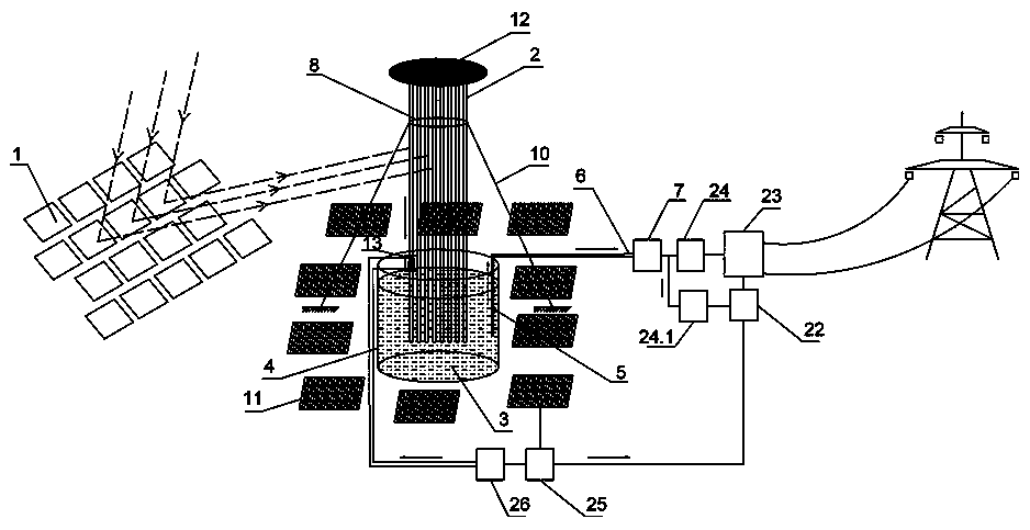
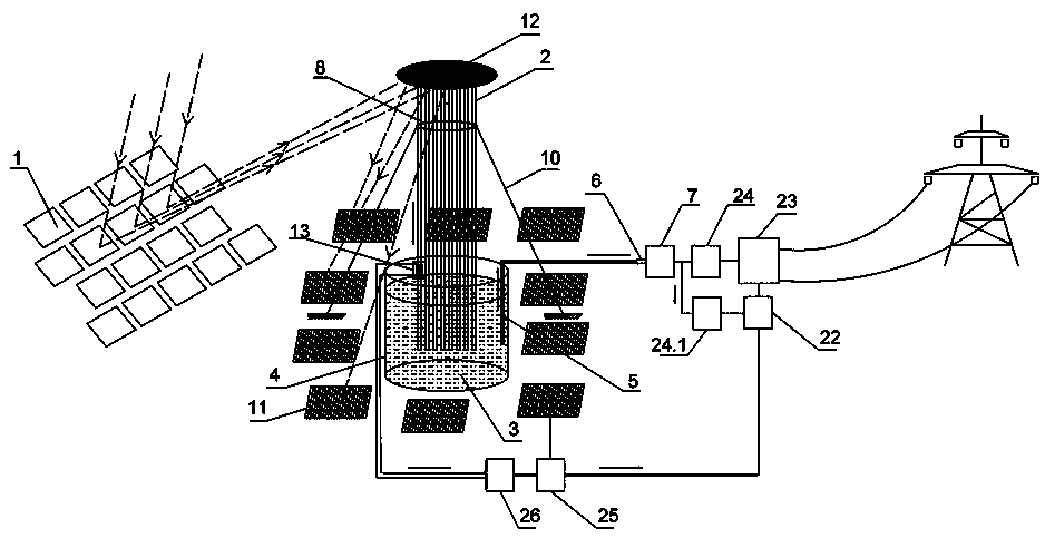
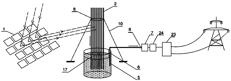
[0028] The direct heat absorption energy storage power generation system based on vacuum heat absorption tubes in the present invention includes a solar thermal power generation system and a solar photovoltaic power generation system.

[0029] Such as Figure 1-4 As shown, the solar thermal power generation system includes a heat collection system for collecting solar heat energy, a heat storage system for storing heat energy, and a power generation system for converting heat energy into electrical energy; the heat collection system includes a plurality of heliosta...


PUM


Abstract

The invention discloses a direct heat absorption type energy storage power generation system based on vacuum heat absorbing tubes. T the direct heat absorption type energy storage power generation system comprises a heat collection system, a heat storage system and a power generation system. The heat collection system comprises heliostats and a vertical heat absorption tube array. The heat storagesystem comprises a heat storage tank. The power generation system comprises a heat output conductor, a heat switch, a steam turbine and a power generator. The lower portion of the vertical heat absorption tube array extends into a heat storage medium. The other end of the heat output conductor makes contact with a steam generator heat exchange pipeline of the steam turbine through the heat switch. The output end of the steam turbine is connected with the power generator. The direct heat absorption type energy storage power generation system adopts a photo-thermal power station heat absorptionand heat conduction mode, directly absorbs sunlight through the heat absorption tubes, transmits heat to the heat storage medium in the heat storage tank on the ground without delivering the heat storage medium to a tower top. Application of an existing molten salt pump and flowing of the heat storage medium are avoided. The cost is substantially reduced. The safe reliability of the system is improved.

Description

technical field [0001] The invention relates to an energy storage power generation system, in particular to a direct heat absorption type energy storage power generation system based on a vacuum heat absorption tube. Background technique [0002] With the increasingly tense energy supply and global carbon emission restrictions, solar energy, as an inexhaustible clean energy, is expanding its application fields. Solar photovoltaic power generation and solar thermal power generation are the mainstream development directions of solar energy applications. Solar thermal power generation uses a high-precision concentrator to gather low-density solar energy into high-density thermal energy, and drives a generator by heating the working fluid to achieve photoelectric conversion. [0003] The tower-type photothermal power generation system using molten salt as the heat transfer medium has the advantages of large power, high efficiency, strong heat storage capacity, and stable operati...

Claims


Application Information

Patent Timeline
IPC IPC(8): F01D15/10F03G6/06F24S60/00F24S10/40H02S40/44
CPCH02S40/44F01D15/10F03G6/068Y02E10/46Y02E10/50Y02E10/60
Inventor 杨大楼
Owner 杨大楼
Learn More